|
|
HISTORICAL MINIATURES BY GEORGE GRASSE |
|
|
|
HISTORICAL MINIATURES BY GEORGE GRASSE |
|
|
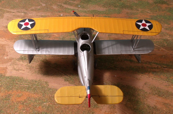
VOUGHT O2U-1 "CORSAIR" of VS-5S c. 1927-1935 |
by George Grasse

WINGS MODELS 1:48 SCALE VACU-FORMED MULTI-MEDIA KIT WM48008 OF THE VOUGHT 02U-1 "CORSAIR", SHIPBOARD OBSERVATION FLOAT PLANE OF VS-5S, LIGHT CRUISER U. S. S. RALEIGH
|
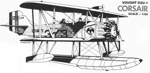
WINGS MODELS VOUGHT O2U-1 "CORSAIR" BOX
ART
|
 |
|
This image of the kit's "box art" shows Vought O2U-1 "Corsair" A-7536 of Observation Squadron 3 (VO-3S for short) of the light cruiser USS Raleigh (CL-7) in 1927, the year the "Corsair" was first deployed to the fleet. The image is based on a photo that appears in U.S. Navy Aircraft 1921-1941 & U. S. Marine Corps Aircraft 1914-1959", page 58.1 The photo is also the basis for a good color profile appearing in "Wings of the Fleet - US Navy & Marine Corps Aviation 1919-1941", page 31.2 When not serving aboard ship and based on land, float gear was replaced by landing gear. |
|
VOUGHT O2U-1 "CORSAIR" THREE-VIEW
|
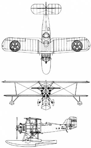 |
| This image is taken from the Aviastar website and shows the landing gear arrangement superimposed on the float gear. |
|
VOUGHT O2U "CORSAIR" SERIES U. S.
NAVY/U. S. MARINE CORPS /U. S. COAST GUARD "A" PREFIX BUREAU NUMBERS
|
||||||||||||||||||||||||||||||||||||||||||||||||||
|
A total of 291 O2U series aircraft were
delivered to the U. S. Navy/U. S. Marine Corps/U. S. Coast Guard. This list excludes Vought O2U Series
aircraft sold to other than the USN/USMC/USCG, namely 88
aircraft sold to foreign
countries and private institutions. This brought total production to
379 O2U series aircraft. The series was improved to subsequent
models, namely the O3U, O4U, and SU variants but they are not
considered here.
3
|
|
O2U "CORSAIR" HISTORY
|
||||||||||||||||||||||||||||||||||||||||
|
In the second half of 1926, the U. S. Navy
issued a contract for the first Vought O2U-1 powered with the new
Pratt & Whitney R-1340B radial engine. In late November 1926.
the first flight was made and deliveries began shortly after.
The first squadron to take delivery was VO-7M on 17 December 1927.
The production run for the O2U series would run until 1931 numbering
291 aircraft of the O2U-1, -2, -3, and -4 variants. The last
reported aircraft in squadron service was an O2U-2 belonging to
VB-2B on 30 April 1936.
4 In 1926, the total number of U. S. Navy aircraft totaled 888 of which 600 were combat aircraft and 288 classified as other (mostly trainers, some transports, and a few miscellaneous). The following table illustrates the growth of Naval Aviation during the service life of the O2U series with comparisons to World War II levels. 5
The O2U-1 broke several world records. On 14 April 1927, it broke the altitude record at 22,178 feet. On 23 April 1927, it broke the 100 kilometer (km) speed course record at 147.263 mph. On 30 April 1927, it broke the 500 km speed course record at 136.023 mph. On 21 May 1927, it broke the 1000 km speed course record at 130.932 mph. 6 The point here shows the technical advance by Pratt & Whitney in engine development and the fact that a two-seater for that time out-performed all other naval aircraft albeit briefly. The O2U was intended as a single-engine, two-seat float aircraft to operate as a catapult observation aircraft for beyond-the-horizon reconnaissance. The year 1930 was the last year in which the O2U series was the primary observation aircraft of the fleet. In 1931, the O3U was taking over as observation aircraft on most battleships of the fleet and the O2U was appearing more often as a utility aircraft or squadron "hack". This would last well into 1936 when the first Grumman JF-1 "Duck" and Curtiss SOC appeared as the new utility and observation aircraft, respectively. By 1938, the Curtiss SOC series was the dominant observation aircraft of the fleet. When introduced in 1926-27, the Vought O2U series maintained a service life of about ten years making it quite successful as a float observation aircraft for the U. S. Navy and a land-based two-seater scout-bomber for the U. S. Marine Corps. 7 |
|
UNDER CONSTRUCTION PHOTO #1
20 April 2012
|
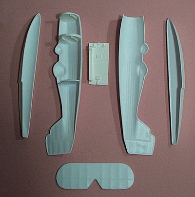 |
| THE BEGINNING: This is my first vacu-form kit and aside from the known amount of work involved I am interested in trying out this form of 1:48 scale aircraft modeling. Most of the detailed parts, the struts, and engine are not worth the effort. Fortunately, Wings Models includes a white metal radial engine and I have experience making my own brass tube/brass rod struts and cockpit details. In this view, I glued the front fuselage and front cockpit formers in place. I made another former for the rear cockpit. The floorboard fits nicely between the two. Now I have to consider internal cockpit detail before gluing the two fuselage halves together. Before starting, I suggest that the modeler review John Lester's review of this kit on the internet.8 |
|
UNDER CONSTRUCTION PHOTO #2
20 April 2012
|
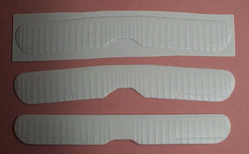 |
| WINGS ARE STARTED: This view shows at the top the rough cut-out of one half of the upper wing. The middle photo shows the other half trimmed and thinned at the trailing edge ready for gluing to the top. The bottom is the lower wing glued together. It will be cut in half to fit into the bottom of the fuselage. The plastic material is soft enough to cut and sand without too much trouble. |
|
UNDER CONSTRUCTION PHOTO #3
14 May 2012
|
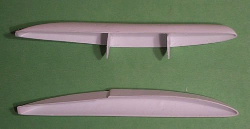 |
| REINFORCING THE MAIN FLOAT: The image at the bottom of the photo shows the one half of the float section cut from the vacu-formed sheet, trimmed, and sanded. The other half was similarly done and fitted together for a match. The upper image shows two reinforcing bulkheads glued in place. They were made from leftover vacu-formed cut-offs. |
|
UNDER CONSTRUCTION PHOTO #4
17 June 2012
|
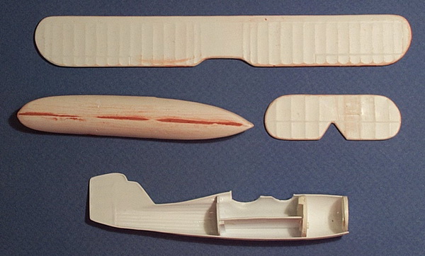 |
| MAJOR COMPONENTS WELL UNDERWAY: The top piece is the completed lower wing which has been glued together (top and bottom), filled with putty, and sanded. The main float is now glued together, filled with putty, and sanded. The same procedure was used on the horizontal tail. In the bottom of the photo is shown the beginning of cockpit interior detail. The engine bulkhead was glued in place first after trial fitting with both halves of the fuselage. The forward and rear cockpit bulkheads were done likewise. Small plastic cleats made from stock material were glued to support the floorboard which was made from leftover vacu-formed plastic sheet. |
|
UNDER CONSTRUCTION PHOTO #5
23 December 2012
|
|
|
| FUSELAGE HALVES JOINED: I should have photographed both fuselage halves showing the interior detail work added. I used Eduard's pre-painted PE sheet FE303 for the SBU2-3 Vindicator. The fuselage halves went together easily and dried over night with the aid of rubber bands. Putty was applied to the seam lines and sanded down with 300 grit sandpaper. |
|
UNDER CONSTRUCTION PHOTOS #6a and 6b
23 December 2012 |
|
|
|
|
| COCKPIT INTERIOR PHOTOS: These two photos show some of the detail I added to the interior. The kit's vacu-formed seats were cut out, trimmed, and painted with Vallejo VC0864 Natural Steel. The lap belts were from the Eduard Vindicator PE sheet. The shoulder belts were made from sheet lead foil and painted with Vallejo VC0914 Green Ochre, a close match to the Eduard pre-painted belts. All of the instrumentation in the photos comes from the same Eduard Vindicator PE sheet. All interior surfaces including the floor were painted with Vallejo VC0907 Light Pale Glue Gray. Many panel lines and other details were lost during the sanding process. Incidentally, I used Vallejo VC0401 Plastic Putty (tube) on this model. It dries to a harder finish than a putty filler such as Green Putty or Model Master's Red Putty. | |
|
UNDER CONSTRUCTION PHOTO #7
26 December 2012
|
 |
|
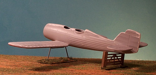
FLYING SURFACES ADDED: The fuselage has the
slightest of imbedded "cross-hatched lines" that identify the
location of the lower wing and horizontal tail. First,
however, each of these has to be cut in half. The cross
hatching marks for the lower wing halves was cut out with an X-Acto
#11 bladed tool. This took more than just a few "cut and fit"
iterations for fear of over-cutting and leaving a large unwanted
gap. Finally, the fit was quite good. I used plastic
cement for most of the gluing but used super glue underneath along
the wing-fuselage seam to speed up the the process and get the wings
in the correct configuration. This was done completely by "eye
ball". The tail was a different story. I decided to forego the cutting out process and, instead, opted for a brass pin, plastic cement, and a little super glue. I'm not disappointed in my first vacu-form kit. |
|
UNDER CONSTRUCTION PHOTO #8
9 January 2013
|
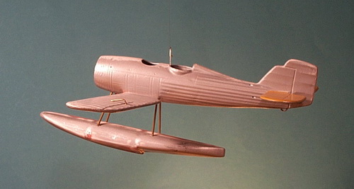 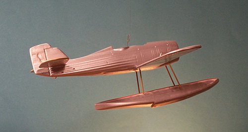 |
| MAIN FLOAT ATTACHED: Two views of the attached main float. The struts were made from brass tubing through which a smaller diameter brass rod was inserted. The rods protruded from both ends of the strut to serve as anchors. Before the actual attachment, I pre-drilled all of the holes for the rigging on the fuselage underside and float topside. The object sticking up in the rear cockpit is a brass rod in the shape of a hook attached to .005 monofilament thread so I could suspend the model for these photos. |
|
UNDER CONSTRUCTION PHOTO #9
9 December 2013
|
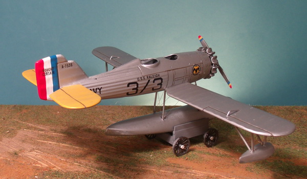 |
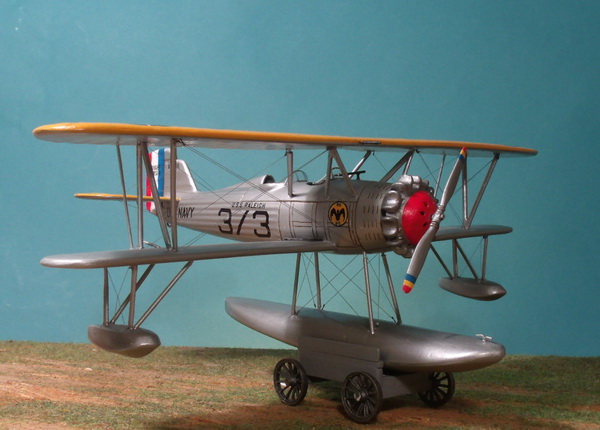
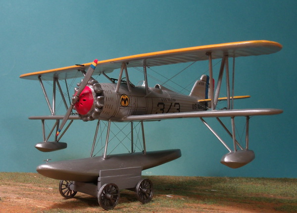
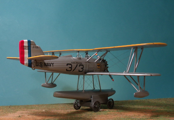
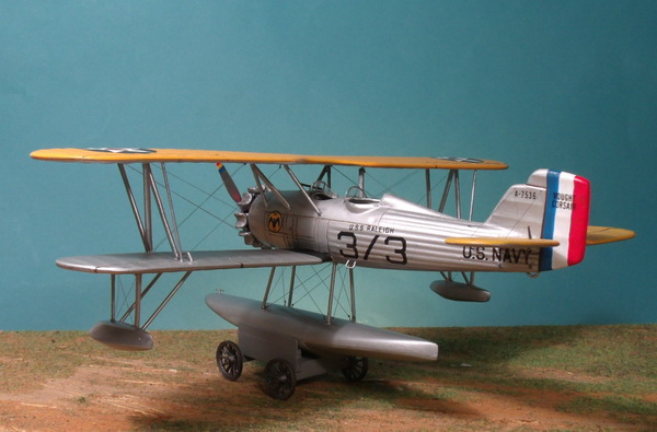
| WORK IS RESUMED: Almost one year later than the panel above, I resumed work on the Vought O2U-1 Corsair. This photo and the following three (photos 9 thru 12) summarize the work I've done in December 2013. Panel 8 above shows the Corsair in its overall aluminum finish (Tamiya TM8017 Aluminum Silver). I painted the upper surfaces of the tail unit and top wing (not shown) with Tamiya's TM8034 Camel Yellow and darkened the elevator hinge line with a dark brown/black liner. The rudder colors were hand painted using Vallejo acrylics (VC0947 Red, VC0951 White, and VC0963 Medium Blue). The same colors were used to paint the propeller tips except that Vallejo VC0953 Yellow was used as the center color. |
|
UNDER CONSTRUCTION PHOTO #10
9 December 2013
|
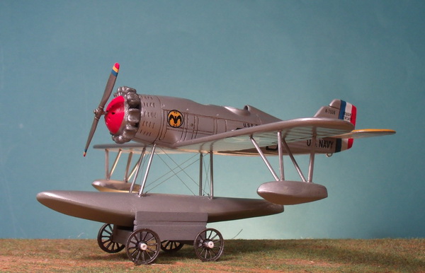 |
| THE ENGINE: I went to work on the engine concurrently with a number of other tasks and finished the cast metal engine supplied with the kit to replace its poor vacu-form engine. The engine warming plate had to be drilled out. Its purpose was to accelerate warming of engine oil when the air vents were closed. During flight, the air vents were opened. I just might add additional detail now that the engine is in place and looks pretty simple as shown. The propeller is also metal and needs to be seated a little deeper than shown. |
|
UNDER CONSTRUCTION PHOTO #11
9 December 2013
|
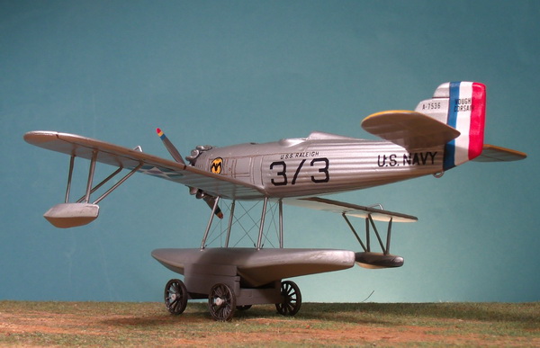 |
| MAKING A FOUR-WHEEL FLOAT TROLLEY: The kit does not supply a land trolley so I built one to my imagination using 25mm Minifigs small wagon wheels and plastic bar stock. The trolley was painted Vallejo VC0870 Medium Sear Gray. The wheels were painted in a mix I labeled "Iron". This view shows to great effect the rigging detail of the main float. |
|
UNDER CONSTRUCTION PHOTO #12
9 December 2013
|
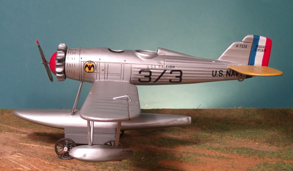 |
| DECALS: The decals that come with the kit represent a Corsair from the U. S. S. Raleigh, a heavy cruiser. I painted a yellow circle as background for the squadron insignia. After the decals were applied, I sprayed the model with satin polyurethane. |
|
UNDER CONSTRUCTION PHOTO #13a
31 March 2014 |
 |
|
TOP WING ATTACHMENT, RIGHT SIDE VIEW: The
Corsair's wing struts are splayed outwards and there is a slight
stagger. This panel (13a) describes how the struts were made;
the panel below (13b) describes the top wing attachment. In most of my biplane kit builds, I substitute kit struts for hand-made brass struts. The finished strut is a flattened, aerodynamic brass tube with a brass rod insert. The insert prevents the brass tube from collapsing during the light hammering process and the inserts, which protrude from both ends, serve as attachment points to the wings. |
|
UNDER CONSTRUCTION PHOTO #13b
31 March 2014
|
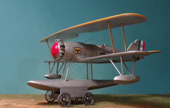 |
| TOP WING ATTACHMENT, LEFT SIDE VIEW: The wing struts measure exactly the same according to the front view of the kit's drawings. Each strut was super glued in place with a slight stagger forward and an outward "splay". When dry, the top wing was mounted. Some additional bending of the a couple of struts was required to get the top centered from the front and from above according to the drawings. Each was given an additional dot or two of super glue. The loose monofilament thread are all of the rigging wires for the wing bays. The top wing has a slight bow in the center but the attachment of the cabane struts later will bring the top wing into alignment. |
|
UNDER CONSTRUCTION PHOTO #14
3 April
2014
|
 |
| STRUTS COMPLETED: This photo shows all of the brass tube/rod struts in place. They will be primed and painted. |
|
UNDER CONSTRUCTION PHOTO #15a
5 April
2014
|
 |
| RIGGING AND DETAILS: Rigging with .005 monofilament thread is completed. Windscreens for the pilot and observer/gunner are installed. I used an old Nieuport 16 windscreen for the pilot and fashioned one from clear sheet plastic for the observer/gunner. All of the struts have been primed and painted with Misterkit MKFC01 French WW1 Aluminum. Note also the foot step below the rear cockpit fashioned from brass rod. Barely visible at the front of the main float is the docking cleat also fashioned from brass rod. On each side of fuselage root is a hand-painted matt black wing walk. |
|
UNDER CONSTRUCTION PHOTO #15b
5 April
2014
|
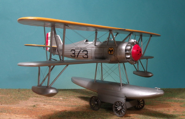 |
| MORE DETAILS: The docking cleat on the bow of the main float is clearly visible. At the rear of each wing strut is an aileron strut made from brass rod. The U. S. Navy version had a single top wing mounted .30 caliber machine gun located to the right of the center line. It is somewhat visible as a black line just above the space between the pilot's windscreen and the engine. |
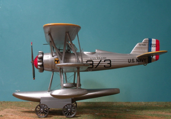
FINISHED PHOTOS
 |
 |
 |
 |
 |
 |
FOOTNOTES
1 Larkins, William T. U. S. Navy Aircraft 1921-1941 and U. S. Marine Corps Aircraft 1914-1959. The year-by-year U. S. Navy section of this book concludes each year with an aviation deployment schedule of all aircraft on ships of the fleet. USS Raleigh (CL-7) was part of the U. S. Navy's Scouting Fleet in 1927. In 1928, VO-3S changed its designation to VS-5S and furnished catapult-launched O2U-1 and UO-1C scout aircraft to Light Cruiser Divisions Two and Three consisting of the USS Concord, USS Cincinnati, USS Detroit, USS Marblehead, USS Richmond, and USS Raleigh.
2 Freeman, Peter. "Wings of the Fleet - US Navy & Marine Corps Aviation 1919-1941", page 31. The insignia of OS-3S and later VS-5S was a black bat on a black-outlined yellow circle with VO at the top and 3S at the bottom in black. Note also black "3 / 3" identification which uses the forward slash instead of "O" for ease of recognition. Each ship to which an observation aircraft belonged displayed the ship's name above the identification, in this case "USS Raleigh" in black.
3 The Vought Heritage website, covers all Vought "products" including the O2U with a brief history of the series, a production table (by year, model, and customer), specifications for the land and seaplane versions, and several photos.
4 Pearson, Lee M. and Adrian O. Van Wyen, United States Naval Aviation 1910-1970 (NAVAIR 00-80P-1), Appendix V, pages 320-321. The Pratt & Whitney R-1340B was revolutionary and powered the O2U-1 and -2. The engine was upgraded to the R-1340C for the O2U-3 and -4 but overall output rating remained at 450 hp (engine information from Larkins' book, U. S. Navy Aircraft 1921-1941 and U. S. Marine Corps Aircraft 1914-1959 page 332).
5 ibid, Appendix V, pages 299-300. Aircraft carrier information is taken from Appendix III, pages 287 and 297.
6 ibid, Part II, page 61.
7 Larkins, William T., ibid, pages 90-229 but primarily the year deployments 1930-1938 within those pages.
8 Lester, John. Wings 1/48 Vought O2U 'Corsair', internet article (see bibliography). Not a builder's review but just the kit itself is discussed. Probably written in the late 90s/early 2000s when the kit's price was $19.95 (today's price in 2012 is $33.95 available from Don's Model Works, http://www.donsmodelworks.com/index.htm).
BIBLIOGRAPHY
Freeman, Peter and Mike Starmer. Wings of the Fleet - US Navy & Marine Aviation 1919-1941, On Target Special. Ardington, North Wantage, Oxfordshire, UK: The Aviation Workshop Publications, 2010.
Larkins, William T. U. S. Navy Aircraft 1921-1941 / U. S. Marine Corps Aircraft 1914-1959. Atglen, PA: Schiffer Military/Aviation History, 1995.
Lester, John. "Wings 1/48 Vought O2U "Corsair", Modeling Madness kit review, http://modelingmadness.com/reviews/preww2/lesero2upreview.htm
Pearson, Lee M. and Adrian O. Van Wyen. United States Naval Aviation 1910-1970 (NAVAIR 00-80P-1). Washington, D. C.: U. S. Government Printing Office, 1970.
Vought Heritage Website at http://www.voughtaircraft.com/heritage/index.html.
GO TO?