|
|
HISTORICAL MINIATURES BY GEORGE GRASSE |
|
|
|
HISTORICAL MINIATURES BY GEORGE GRASSE |
|
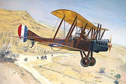
ROYAL AIRCRAFT FACTORY BE.2c, No.1741, No.12 Sqdn RFC 1916
by George Grasse

|
RODEN 1:48 SCALE PLASTIC INJECTION KIT RO0426 of the RAF BE.2c |
|
RODEN RO0426 BOX ART
|
 |
|
ROYAL AIRCRAFT FACTORY
BE.2c THREE-VIEW DRAWING
|
.jpg) |
| This 3-view drawing is credited to J. D. Carrick or F. Yeoman and appeared in Reconnaissance and Bomber Aircraft of the 1914-1918 War compiled by W. M. Lamberton and published by Harleyford Publications Limited. The BE.2c went to war in 1914 as a stable reconnaissance platform. The Fokker Scourge in mid-1915 exposed an extremely ill-armed, minimally evasive and otherwise vulnerable aircraft. Production of newer types was well into the future and the BE.2 series in general bore a significant reconnaissance burden that cost heavy casualties until newer, up-to-date aircraft could be delivered. |
|
THE
MODEL TO BE BUILT - PROFILE
|
%20No.%2012%20Squadron,%20RFC,%20France%201916%20(Br%20Two-Seaters,%20Bar,%20pg.028).jpg) |
| BE.2c Nr.1741 of RFC No. 12 Squadron was flown by Lieutenant C. O. Fairbairn (P) and Captain E. C. Perrin (O) on a reconaissance mission to the Bruges, Belgium area, 19 december 1915, in coincidence with a heavy German gas attack on part of the British 2nd Army front. While performing that duty, Nr. 1741 engaged a German Albatros two-seater aircraft and, after a 10-minute duel, appeared to have wounded the German observer near Yrpes-Poperinghe and the enemy flew or dived away allowing Fairbairn and Perrin to make an aerial victory claim. However, their aircraft was apparently badly shot up and Fairbairn wounded in the arm. As a result, No. 1741 retired to and landed safely west of their own lines. This narrative is interpreted from The Sky Their Battlefield, page 63 (see bibliorgraphy below). The color profile was produced by Ronnie Bar and taken from his book British Two-Seaters of the Great War (see bibliography below) |
|
THE
MODEL TO BE BUILT - PHOTO
|
%20%20(RAF%20BE2C,%20DF%2042,%20JM%20Bruce,%20Alb%20Prod,%20pg.009).jpg) |
| BE.2c Nr.1741 is shown at an unidentified location and unknown period of time. It does support the general appearance of the aircraft as shown in the profile above. According to the caption with this photo which is dated 6 February 1916 some time after the engagement of 19 December 1915, the second Lewis gun was an experimental fitting completed after the 26 January 1916 date on which No.1741 was repaired. I will not add a second Lewis gun so as to depict the aircraft as might have appeared in the engagement. This photo is taken from Windsock Datafile 42, RAF BE2C, by J M Bruce, produced by Albatros Productions Ltd (see bibliography below). |
|
CONSTRUCTION PHOTO No. 1
|
|
|
| GETTING STARTED: This view shows the kit's interior nearly all in place so it's too bad more detail was not provided. |
|
CONSTRUCTION PHOTO No.
2
|
|
|
| The instrument panel was enhanced with a number of Eduard WW1 instruments. |
|
CONSTRUCTION PHOTO No.
3
|
|
|
| This closeup shows the flooring and mechanical components of the pilot's control stick attached to the bottom wing. |
|
CONSTRUCTION PHOTO No.4
|
| |
| Lower wing and horizontal tail are glued to the fuselage. |
|
CONSTRUCTION PHOTO No. 5
|
| |
| This view shows progress to date. |
|
CONSTRUCTION PHOTO No. 6
|
| |
| Tailskid replacement. Why? The kit's plastic parts broke almost immediately their being so weak. I resorted to two 'V' shaped brass pins for the outside support. I fashioned a brass tail skid and soldered it between the 'V' supports. I made a spring coil from copper fuse wire. The coil as shown was attached using super glue and was still setting up when the photo was taken. I'll make adjustments to the spacing later. |
|
CONSTRUCTION PHOTO No.7
|
| |
| The model to date is now supported by front brass landing gear and the scratch-built tailskid. The V-8 engine and its cowling were easily set in place for a trial fit then glued. The dark gray wheel covers and engine cover will be re-painted in a lighter gray. |
|
CONSTRUCTION PHOTO No.8
|
| |
| The center section fuselage struts will be finished as brass rod with flattened brass tube. For now, the trick is to get the exact sizing of the struts which is shown in the photo above. |