|
|
HISTORICAL MINIATURES BY GEORGE GRASSE |
 |
|
|
HISTORICAL MINIATURES BY GEORGE GRASSE |
 |
|
SPAD SA.2 No. S.31, Escadrille N.73 early 1916 |
by George Grasse
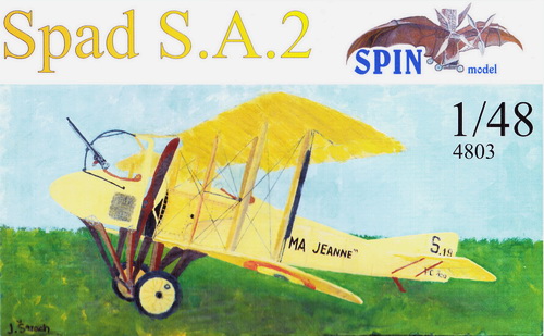
SPIN MODELS 1:48 SCALE RESIN KIT 48003 OF THE SPAD SA.2

|
SPIN MODELS 48003 BOX ART
|
 |
|
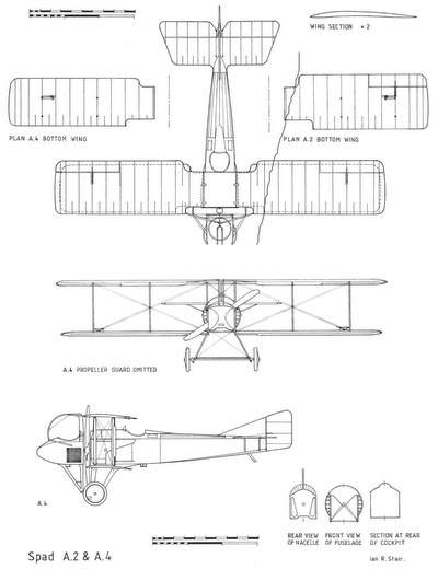
SPAD SA.2/SA.4 3-VIEW DRAWING
|
 |
| This 3-view drawing is credited to Ian Stair and appeared in The Imperial Russian Air Service: Famous Pilots and Aircraft of WW1 by Thomas Darcey, Alan Durkota, and Victor Kulikov published by Flying Machines Press 1995. The Spad SA.4 was the export (Russia) version of the French SA.2. The major outward difference being the narrow chord lower wing for the SA.4. As in France with the SA.2 version, these somewhat odd aircraft were assigned to flying units as individual aircraft. More reference information is available in the bibliography section below. |
|
THE
MODEL TO BE BUILT
|
.jpg) |
| The model to be built is Spad SA.2 serial number S.31 of Escadrille N.73 in early 1916. The photo shows S.31 parked among Nieuport 11 aircraft of the escadrille. It is finished in the French 'yellow' scheme in which metal parts had a deeper 'yellow' shade than fabric-covered surfaces. I selected this specific aircraft because it is the only officially recorded Spad SA.2 that achieved an aerial victory. It was crewed by Corporal Sabatier (pilot) and Corporal Funck-Brentano. |
|
PHOTO OF SPAD SA.2 No. S.31
|
.jpg) |
| The above photo is taken from SPAD Two-Seat Fighters page 53 (see bibliography below). This closeup view emphasizes the feature-less finish of this particular aircraft. You can see the upper top wing roundels through the opaque fabric and the underside roundels just barely visible. The armament was a French-built Lewis machine gun. The figure on the ground is probably the aircraft's chief mechanic with his left hand on the propeller. |
| CONSTRUCTION
PHOTO #1
2024
|
| The instrument panel is improved with the liberal use of Eduard WW1 instruments. Strips of piano wire and plastic represent control wires and electrical lines that will be coverred when the seat assembly is installed. Not much will be seen once the fuselage halves and glued together. |
| CONSTRUCTION
PHOTO #2
2024
|
| The fuselage halves are bonded together, caulked with plastic putty, and sanded. The front gunner's cockpit is just glued together for now. Note the seat that will be installed with additional scratch-built "things" and spare drums for the Lewis gun. |
| CONSTRUCTION
PHOTO #3
2024
|
| The front nacelle has the PE propeller guard glued in plance and the inside is painted aluminum. The main fuselage has to have the rotary engine installed first beforee the PE front piece is glued. |
| CONSTRUCTION
PHOTO #4
2024
|
| This view shows the back of the nacelle and front of the fuselage. |
| CONSTRUCTION
PHOTO #5
2024
|
| Before the lower wing halves can be joined, the landing gear needs to be in place. Note the join of the fuselage and upper landing gear edge. The slightly concave area is where each lower wing half fits. I seriously considered re-making the entire landing gear from brass rod and tube but the complexity and shape of each "leg" would have been difficult. I went ahead and glued the two resin landing gear "legs" in place. I discarded the kit's spreader bar and made my own from three pieces of brass rod covered by lead sheet as shown in the photo above. The pulpit was worked on as well. The seat was finished with added seat belts and paint and carefully inserted. Not quite visible is an epoxy-made head-rest. |
| CONSTRUCTION
PHOTO #6
2024
|
| As noted above, the landing gear struts have to be in place before the lower wings can be attached simply because the struts are part of the attachment point for the wings. Each wing was placed against its attachment point and pencil marks were made for brass wire lengths that will reinforce the wing-to-fuselage attachment. Two holes were drilled into each lower wing edge and corresponding holes were drilled into the fuselage. I test fit the wings and cut the brass rods to length for the best fit. Super glue was used to finish the attachment. The tail was worked on next. I discarded the kit's flimsy resin "rods" intended for support and used some old "Strutz" material. I next pre-painted the rudder stripes then glued the fin/rudder unit onto the tail. Wheel covers were painted with Humbrol 103 Matte Cream. I used my own mix of pinkish-gray for the tires. The brass rod for the axle was trimmed to fit the depth of the wheel holes. Now, it's starting to look like a Spad! |
| CONSTRUCTION
PHOTO #7
2024
|
| All of the inter-wing and wing/fuselage rigging starts by drilling all of the rigging holeds. Then, a length of mono filament thread is super-glued into each hole resulting in the mess shown above. |
| CONSTRUCTION
PHOTO #8
2024
|
| The kit's struts were discarded and substituted with brass rod and tubing as shown above. The fuselage interplane struts are attached because that's the first step in top wing attachment. The wing struts are cut at each end to simulate the actual taper of the struts. The middle struts are notched for the addition of a bracing strut. The brass rods are .81mm by K & S Metals. The brass tubing is 1.5mm OD x 1.3mm ID by Albion Alloys. |
| CONSTRUCTION
PHOTO #9
2024
|
| The top wing has been attached and rigged. The light gray coloring on the outside rear wing strut shows the attachment of the PE aileron control strut. The forward edges of the landing gear struts were modified by adding scrap plastic extensions to compensate for the lack of strength in the kit's landing gear struts. By this I mean that the forward axle that allows the front pulpit to swing had to pass through holes drilled through the most forward part of the extended strut arms and that was not enough strength to support the pulpit. The white-colored pieces are the plastic extensions I made. See photo below |
| CONSTRUCTION
PHOTO #10
2024
|
| The construction of the 'pulpit' was not preserved in photos which I forgot to take. The struts are brass rod and tube attached to the bottom of the 'pulpit'. Two small holes were drilled into makeshift plastic supports through which a small brass rod is passed. This rod allows the 'pulpit' unit to be rotated down to the ground thus exposing the rotary engine for repair and maintenance. The pulpit when upright as shown in the photo, it engages rods and a locking mechanism to hold it in place during flight. |
| CONSTRUCTION
PHOTO #11
2024
|
| This view shows the completed model. The mid-blue rod attached to the outside rear wing strut transfers control stick activation for aileron control to the upper and lower ailerons. Decals to the rudder were made on the computer. The gloss from the decal was corrected with paint touch-up. The kit did not address the mounting of the Lewis gun and it was placed in the appropriate position. |
| CONSTRUCTION
PHOTO #12
2024
|
| The aileron actuating rod is shown on the right outside read wing strut. |
| CONSTRUCTION
PHOTO #13
2024
|
| CONSTRUCTION
PHOTO #14
2024
|
| CONSTRUCTION
PHOTO #15
2024
|
| CONSTRUCTION
PHOTO #16
2024
|
.jpg) |
------------------------------------------- finis -------------------------------------
Bibliography:
Blume, August G. The Russian Military Air Fleet in World War I, volume 2: Victories, Losses, and Awards. Atglen, PA: Schiffer Military History, 2010.
Bruce, J. M. SPAD S.A-2/S.A-4, Windsock Mini Datafile 4. Berkhamstead, UK: Albatros Productions, Ltd, 2000 (reprint).
Conners, John F. SPAD Fighters in Action, Aircraft Number 93. Carrollton, Texas. Squadron/Signal Publications, 1989.
Davilla, James J Dr. and Arthur M. Soltan. French Aircraft of the First World War. Flying Machines Press, 1997.
Herris, Jack. SPAD Two-Seat Fighters of World War I, Great War Aircraft in Profile No. 7. Flying Machines Press, 2005.
Lamberton, W. M., Compiler, and E. F. Cheesman, Editor. Fighter Aircraft of the 1914-1918 War. Los Angeles, CA: Aero Publishers, 1962.
GO TO?
22 September 2024