|
|
HISTORICAL MINIATURES BY GEORGE GRASSE WORLD WAR 1 AIRCRAFT IN 1:48 SCALE |
|
|
|
HISTORICAL MINIATURES BY GEORGE GRASSE WORLD WAR 1 AIRCRAFT IN 1:48 SCALE |
|
FOKKER Dr.I 577/17 of Jasta 27, 1918
by George Grasse
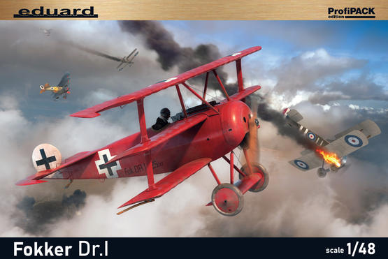
EDUARD 1:48 SCALE INJECTION MOLDED KIT EU8162 FOKKER Dr.I
![]()
|
EDUARD EU8162 BOX ART
|
 |
|
FOKKER Dr.I THREE-VIEW DRAWING
|
.png) |
| This 3-view drawing is credited to J. D. Carrick or F. Yeoman and appeared in Fighter Aircraft of the 1914-1918 War compiled by W. M. Lamberton and published by Harleyford Publications Limited, page 123. Other sources for detailed drawings are listed in the bibliograpy below. |
| THE FOKKER Dr.I 577.17 TO BE BUILT |
.jpg) |
| The model to be built is Fokker Dr.I 577/18 flown by Ltn Rudolf Klimke, Jasta 27, early 1918. The profile above was created by Ronny Bar from his book German Fighters of the Great War, Volume 2, page 135 (see bibliography below). |
| CONSTRUCTION PHOTO #1 |
%2001.JPG) |
| The Hi-Tech kit of the Roland D.II is well molded in plastic and includes a decal sheet and PE fret. Instructions are crude and difficult to follow. This photo shows the start of this project, concentrating on the cockpit for now. |
| CONSTRUCTION PHOTO #2 |
%2002.JPG) |
| The seat rest on a scrap piece of plastic instead of two scrap pieces of plastic rod suggested by the kit's instruction sheet. The seat is a replacement being a bit wider and higher than the kit-supplied one. Seatbelts were taken from an a previously-built model, painted in Vallejo 837 Pale Sand, and highlighted with Vallejo 864 Natural Steel. The fuselage former directly behind the seat was crafted from sheet plastic to eliminate an awkward view of the inside rear of the barren fuselage. The control column and rudder bar are from the kit's PE fret. The red-colored pump, metal utility box, and compass are all add-on pieces. The minor framework was added for looks and to provide a space to which items could be attached. |
| CONSTRUCTION PHOTO #3 |
%2003.JPG) |
| This view shows the kit's forward cockpit former to which are glued the kit's two PE panels at mid-height. Above them are Eduard WW1 insturments variously added The front former has two knotches reserved for the later placement of the machine guns The compass, control column, seatbelts, and rudder control wires show clearly. |
| CONSTRUCTION PHOTO #4 |
%2004.JPG) |
| The cockpit and engine compartments are completed and the fuselage halves are glued together. I used Deluxe Materials (UK) "Perfect Plastic Putty" to fill in the gaps. When drym, the putty was sanded down. A few gaps remained and I decided to use an old plastic model soldier technique for gap-filling. It's a simple mix of turpentine and plastic sprue. Over time, my bottle is 20+ years old, the plastic softens and mixes with the turpentine to produce a liquid plastic filling compound. I left it overnight and lightly sanded the next day. The buff paint is used to see how the seams have filled in. Also, the fuselage had rigging places drilled out. The four pieces that make up the wings were sanded to remove flash, pre-drilled for struts and rigging, and painted in two coats of a Vallejo mix of 961 Sky Blue, a little of 989 Sky Grey, and much more of Andrea AC-01 White. |
| CONSTRUCTION PHOTO #5 |
%2005.JPG) |
| Each half of the lower wing had two brass pins inserted at the wing root to match holes pre-drilled into the wing foots. Attachment of the lower wings was done with super glue and allowed to dry thoroughly. The kit's landing gear struts were replaced with brass tube and rod. Attachment to the fuselage was trial fitted and then secured with super glue. |
| CONSTRUCTION PHOTO #6 |
%2006.JPG) |
| The tail unit has been reinforeced with brass rod. The landing gear axle is glued in place and wired with common copper electrial wire. The spine of the aircraft has been lightly painted in orange ochre to see how the putty and liquid plastic filler blend in. The attachment holes for the top wing brass pins are clearly evident. Note how the rear legs of landing gear struts protrude past the wing root and into the lower fuselage. The landing gear wheels are temporarily added for effect. |
