|
|
HISTORICAL MINIATURES BY GEORGE GRASSE |
|
|
|
HISTORICAL MINIATURES BY GEORGE GRASSE |
|
Rumpler C.I C.1877/15, FFA 17, Western Front, Late Fall 1916
by George Grasse

COPPER STATE MODELS 1:48 SCALE RESIN KIT CS1021 OF THE RUMPLER C.I
|
UNDER CONSTRUCTION
PHOTO #1
27 July 2011
|
 |
|
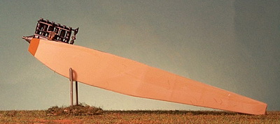
CONSTRUCTION UNDERWAY. The Copper State 1:48 kit is resin except for a few white metal and photo-etched components. This view shows the basic fuselage formed by gluing with super glue the sides to the bottom. The engine was assemble from the white metal kit of the Mercedes D.III. For the time being, it actually just sitting in place. The top of the fuselage comes in to sections and they will be glued in place one I have completed work on the cockpit interior. |
|
UNDER CONSTRUCTION
PHOTO #2
4 August 2011
|
 |
|
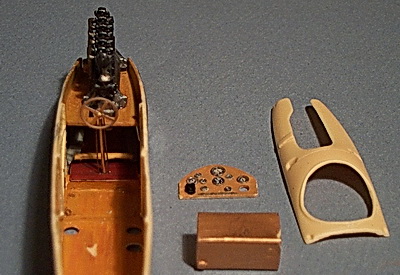
INTERIOR DETAIL STARTED. This Copper State
1:48 kit requires the modeler to make the control column and rudder
bar. In this photo, the rudder bar is seen as the light
colored wood part just behind the control column. The control
column was cut from a length of brass rod and bent at the top to
take the kit's PE steering wheel. The thinner brass rod pieces
on either side of the control column are the aileron control wires.
All of these components sit on top of a scratch-built raised floor
which, on the real aircraft, housed the pulley wheels for the
rudder, elevator, and aileron control wires. I pre-painted a
piece of .010 plastic card stock and stained it in oils to duplicate
grained wood. I chose the darker shade so it would stand out
from the surrounding wood, metal, and fabric materials in the
cockpit.
The instrument panel was built up from both Eduard EU9194 WWI Pre-Colored Instruments and the kit's CS0122 German Gauge Set plus miscellaneous scrap pieces of this and that. I used Aeroclub's ACV242 Beveled Instrument Faces. The brass-painted main fuel tank on which the pilot's seat is to be fitted was cut and trimmed to drop into the fuselage but not until other cockpit details have been added and the interior painted. |
|
UNDER CONSTRUCTION
PHOTO #3
19 August 2011
|
 |
|
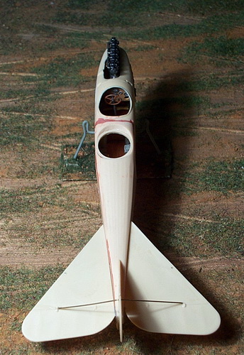
FUSELAGE SEALED UP. I
had a number of cockpit photos before the fuselage was sealed but I
had a serious hard drive failure and missed my backup by a couple of
days and lost those photos. I had already progress to the
stage shown above. Visible in the pilot's cockpit are the
control wheel, instrument panel, and (barely) the rudder bar.
Not visible in this view are left and right side "gadgets",
throttle quadrant, seat, and seat belts.
The observer's cockpit looks bare and the only discernable object is the camera on the right. In the distance can barely be seen the bottoms of the left and right bomb chutes. Not visible are the observer's seat, seat belts, map case, and spare ammunition holder. The tail unit has been added. The left and right tail planes were glued in place first; then, the fin and rudder. I opted not to use the kit's PE tail plane struts and instead cut pieces of brass rod which greatly strengthen the whole tail plane. |
|
UNDER CONSTRUCTION
PHOTO #4
19 August 2011
|
 |
|
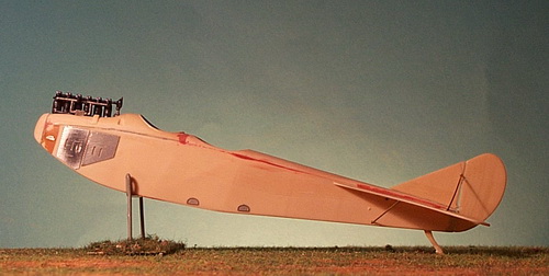
MORE FUSELAGE DETAILS ADDED. This view
shows the putty work on the fuselage which was assembled from two
sides, a bottom, a rear deck which included the observer's cockpit,
the front deck which included the pilot's cockpit and engine
compartment, and, lastly, the nose cowling. This was tricky
work. Except for the nose cowling, each of these components
was partially glued with super glue, aligned, allowed to dry and
another section glued. For example, gluing the left fuselage
side to the bottom required about six separate gluing sessions to
make sure that the slight 45° angle on the inside of the side and
bottom were mated properly. As you can tell by the putty in
the photo above, not all glued points made perfect contact and had
to be filled and sanded. Another problem encountered was the
gluing of the nose cowling and how it interfaced with the engine
drive shaft hole. This took a while and, in the end, required
putty and sanding. Other details added were the tailskid which is usually a piece that I scratch build because they seem so fragile; but, this one is from the kit. The first few pieces from the kit's PE sheet are shown in place. The engine louver openings on the two PE engine side pieces have not had their small covers (also PE) added. Note the tiny nameplate at the front in the orange-brown area just behind the nose cowling. |
|
UNDER CONSTRUCTION
PHOTO #5
2 September 2011
|
 |
|
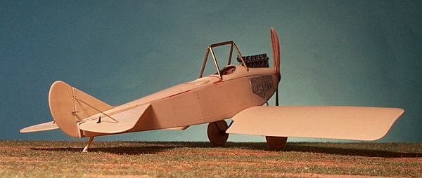
CONTROL HORNS AND CABANE TRESTLE ADDED.
Work on the tail unit was finished by adding the rudder and elevator
control horns using PE parts from Eduard's EU4406 accessory
pack of Wire Stretchers (Turnbuckles) and Control Horns. I
will add the rigging wires after painting the aircraft. The kit's resin inverted "V" cabane trestle was substituted one I built from brass. There are two sides to the trestle assembly and each side is built in the same manner. I used a length of brass tubing from Griffon Models' kit GMBH04 1.0mm outside diameter accessory pack and inserted solid brass rod made by K & S (.51mm diameter). I bent the tubing/rod into the shape of one of the kit's trestle struts. I then "pounded" the piece flat. The brass rod is extended at each opening to serve as a post for gluing to the fuselage and to strengthen the structure so it does not collapse during pounding and approximates the aerodynamic cross-section of the strut. It took a little adjustment to fit but came out to my satisfaction. Note that the lower wings are not glued in place. They have been aligned and pinned but I still have to add fuselage turnbuckles and do a little more work in that area before gluing of the wings. |
|
UNDER CONSTRUCTION
PHOTO #6
2 September 2011
|
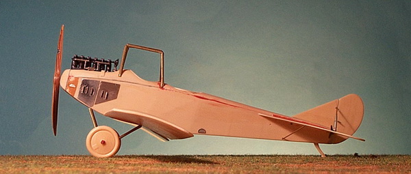 |
| OVERALL SIDE VIEW. Not much to add here. This photo was taken at the same time as Photo #5. You can see the elevator control horns and barely make out the rudder control horns. With your good eye, you can see two small holes drill just above a below the forward edge of the horizontal stabilizer for the elevator control wires. Two more were drilled on the opposite side. An additional two holes were drilled on the top decking for the rudder control wires but they are not visible in this view. |
|
UNDER CONSTRUCTION
PHOTO #7
3 September 2011
|
|
|
| OVERALL UNDERSIDE VIEW. The lower wings are glued now. One coat of brushed-on white primer was thinly applied and then one coat of Misterkit MKGC10 German Clear Doped Linen (CDL) as shown. Landing gear struts and tail unit struts are primed only in this photo. You can see the added spreader bar just behind the axle. |
|
UNDER CONSTRUCTION
PHOTO #8
3 September 2011
|
|
|
| OVERALL UPPER VIEW. The areas still in white primer are metal components that will be painted in German light grey-green, an enamel product used on German World War I aircraft to prevent corrosion. |
|
UNDER CONSTRUCTION
PHOTO #9
7 September 2011
|
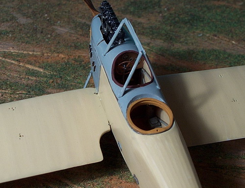 |
| PAINTING THE GERMAN LIGHT GREY-GREEN. All of the areas previously painted in white primer and now painted in German Light Grey Green (Misterkit MKGC08). Note the wing strut and rigging holes pre-drilled on the lower wings; these were drilled through so the rigging wires can be attached to a weight and glue then cut-off. More on that later. |
|
UNDER CONSTRUCTION
PHOTO #10
12 September 2011 |
 |
| UPPER WING UNDER SURFACE. In this view, all of the pre-glued rigging wires are shown. Simple holes were drilled into but not through the wing and a length of .005 monofilament thread was glued into each one. Note that the under surface has been finished in Misterkit MKGC10 German Clear Doped Linen (CDL) |
|
UNDER CONSTRUCTION
PHOTO #11
18 September 2011 |
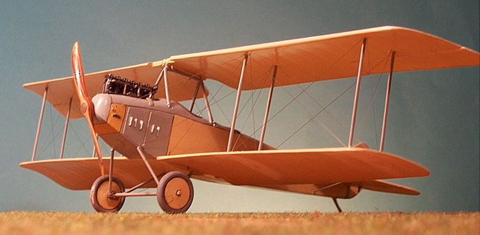 |
| WING ATTACHMENT AND RIGGING. The first step was to join the top of the inverted trestle cabane strut assembly to the top wing balanced by the four inboard wing struts. Each of these struts was first glued only to the lower wing. A generous amount of glue was applied to the top of the trestle which was fit into a make-shift slot of two parallel brass roods and allowed to dry. The top wing was resting on the four unglued wing struts all the time. When thoroughly dry, the struts were carefully positioned into their locating holes on the underside of the top wing. The brass rod projecting from the end of the strut secured each strut into pre-drilled holes. All around the strut holes were drilled the necessary holes for the rigging wires. The outboard group of struts were then glued in place in the same manner: glue one end of the strut, say, to the bottom wing and let it set up. When dry, maneuver the other end into its hold, apply glue, and let it set up. |
|
UNDER CONSTRUCTION
PHOTO #12
18 September 2011 |
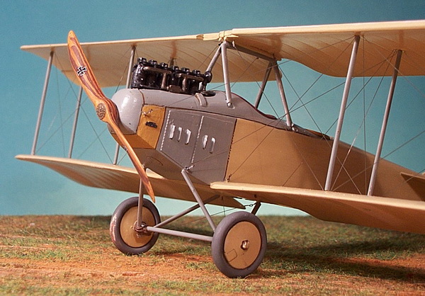 |
| CLOSE-UP OF WING RIGGING DETAIL. PE turnbuckles were used in key positions where a rigging wire terminated. This allowed for the wire to be looped through the turnbuckle eyelet, pulled taut, tied off, and glued. When dry, the excess line was cut away. Other rigging wired originated in the underside of the top wing and passed through a hole in the lower wing where a weight was attached, the rigging glued in its hole, and cut off when dry. |
|
FINISHED
PHOTO #13
20 September 2011 |
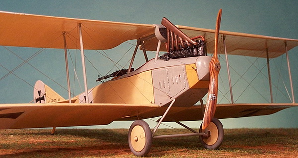 |
| FINISHED MODEL. The final steps included Eisernes Kreuzen decals applied to hand-painted white panels on the wings, fuselage, and rudder. The fin serial number was made using Georgia size 9 font but size 6 font for the "/15". The observer's Parabellum machine gun was built-up from left-over bits and pieces from other kits. So too was the Spandau. I forgot to cut away a slot on the right side of the engine for the recessed part of the Spandau and this had to be carefully done by trial fitting the receiver of the machine gun until it fit properly. The kit's exhaust stack did not fit properly after installation of the Spandau so I retrieved a back-up exhaust stack from my spare parts collection. More finishing details are in the next photo. |
|
UNDER CONSTRUCTION
PHOTO #14
20 September 2011 |
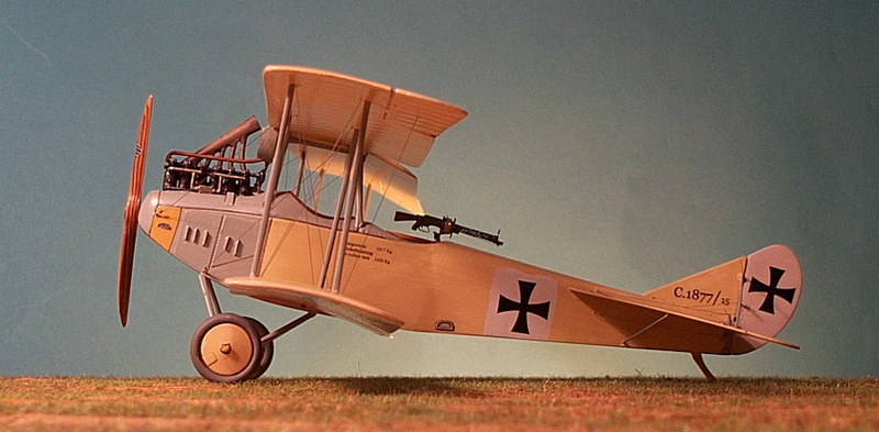 |
| MORE FINISHING DETAILS. One other decal that had to be made is the weight table between the two cockpits. The fin serial number is more clearly shown in this photo. Note the radiator pipe leading to the front of the engine. I painted this with a mixture of Vallejo Copper and Gun Metal Grey. The white EK fields were painted using Misterkit MKGC16 German Off White. The last bit of rigging was the aileron control wires, one on each wing. |
|
THIS MODEL IS FEATURED IN MY HISTORICAL MINIATURES JOURNAL ISSUE #13 WHERE YOU WILL FIND MORE FINISHED MODEL PHOTOS AND BACKGROUND DETAILS OF THIS SPECIFIC AIRCRAFT. CLICK HERE. |
------------------------------------------------ FINIS ---------------------------------------------------
-----------------------------------------------------------------------------------------------------------------
Bibliography:
Gray, Peter and Owen Thetford. German Aircraft of the First World War. London: Putnam & Company, Ltd, 1962.
Grosz, P. M. Rumpler C.I, Windsock Datafile 79, "Fabric - colours and markings" section by Ray Rimmel, color profiles by Ray Rimmel, scale drawings by Ian R. Stair, Albatros Publications Ltd, Berkhamsted, UK, 2000. Excellent for details from a number of other Rumpler C.I and C.Ia aircraft; basic cockpit layout on pages 32; nice cutaway on page 36; another three-view cutaway on page 20.
Heydemarck, Georg Wilhelm. Double-Decker C.666. London: John Hamilton, Ltd, 1934.
GO TO?