|
|
HISTORICAL MINIATURES BY GEORGE GRASSE |
|
|
|
HISTORICAL MINIATURES BY GEORGE GRASSE |
|
|
USAS RAF SE.5a, F.8038, Lt Aubrey 'Joe' Diamond, 25th AERO SQUADRON, 1918 |
by George Grasse

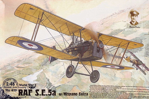
RODEN 1:48 SCALE PLASTIC INJECTION MOLDED KIT RO0419 OF THE SE.5a (Hispano-Suiza)
|
RODEN
RO0419 BOX ART
|
 |
|
ROYAL
AIRCRAFT FACTORY SE.5a THREE VIEW
|
.jpg) |
| This 3-view drawing is credited to J. D. Carrick or F. Yeoman and appeared in Fighter Aircraft of the 1914-1918 War compiled by W. M. Lamberton and published by Harleyford Publications Limited. The British-designed Royal Aircraft Factory SE.5a was adopted by the U. S. Air Service as the pursuit aircraft for its 25th Aero Squadron in late 1918. The squadron had trouble obtaining aircraft and, except for a couple of fail-safe patrols, never engaged in combat when the war ended. |
|
THE
MODEL TO BE BUILT
|
.jpg) |
| The model to be built is RAF SE.5a serial F.8038 flown by Lt Aubrey 'Joe' Diamond, 25th Aero Squadron, assigned as an element of the USAS 4th Pursuit Group. The profile shown above was illustrated by Kevin Wornkey and appeared in S.E. 5a in Action, Aircraft Number 69 published by Squadron/Signal Publications. Except for the serial number and white '11', the aircraft shown is virutally identical to Lt. Diamond's white '15'. |
.jpg)
|
CONSTRUCTION PHOTO No. 1
|
%2001.JPG) |
| The beginning photo shows interior cockpit work. The wood part of the interior is painted in Vallejo 824 Orange Ochre. The fabric portion of the fuselage interior is Vallejo 819 Iraqi Sand lightened with flat white. Other items of the cockpit interior are in various stages of completion, ready to be installed (not all interior parts shown). |
|
CONSTRUCTION PHOTO No.
2
|
%2002.JPG) |
| Here's a photo of the cockpit interior after the fuselage halves were jointed. |
|
CONSTRUCTION PHOTO No.
3
|
%2003.JPG) |
| The fuselage is joined to the bottom wing. At the front end, part of the exhaust and the cowling are cemented in place. |
