HISTORICAL MINIATURES BY GEORGE GRASSE
WORLD WAR 1 AIRCRAFT IN 1:48 SCALE

SALMSON 2.A2 OF THE 12th AERO SQUADRON, U. S. AIR SERVICE, 1918

by George Grasse

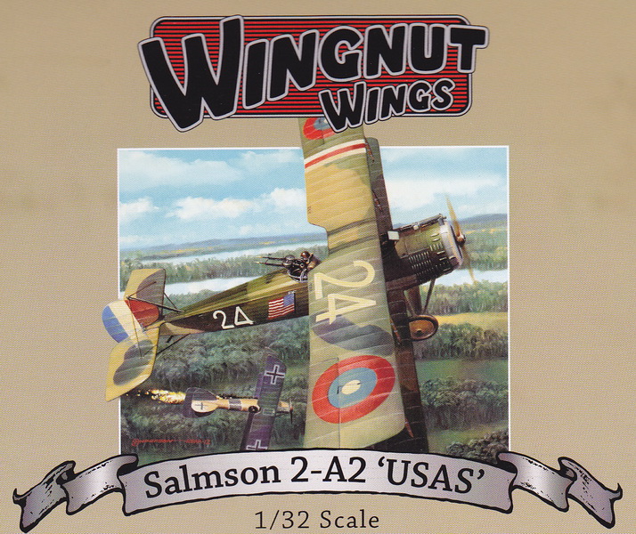
WINGNUT WINGS 1:32 SCALE PLASTIC INJECTION MOLDED KIT WN3059 OF THE SALMSON 2.A2

WINGNUT WINGS WN3059 BOX ART


 SALMSON 2.A2 THREE-VIEW DRAWING

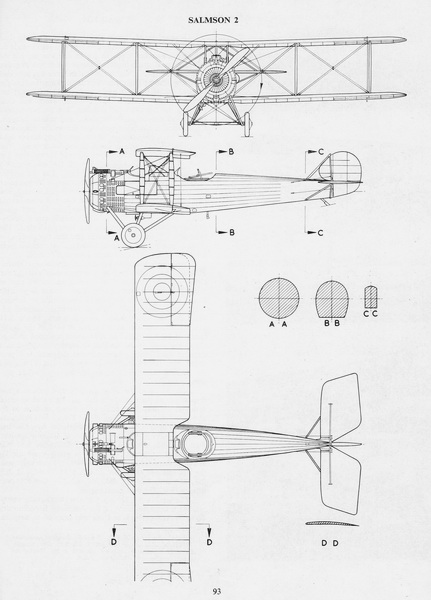
This 3-view drawing is credited to J. D. Carrick or F. Yeoman and appeared in Reconnaissance & Bomber Aircraft of the 1914-1918 War compiled by W. M. Lamberton and published by Harleyford Publications Limited.  The French-designed Salmson 2.A2 two-seat reconnaissance airplane equipped five U. S. Air Service observation squadrons during America's active participation on the Western Front from April to November 1918.  During that period, six USAS Salmson squadrons were active: the 1st,  12th,  24th,  88th, 90th, and 91st.  The 99th and 258th became active in the last weeks of the war bringing the total to eight Salmson squadrons.
 

THE MODEL TO BE BUILT
    
'OLD CAROLINA IV' AND CREW: This photo shows Lt. Dogan H. Arthur (P) and Lt. Howard T. Fleeson (O) and the three principal mechanics of Salmson 2.A2. No. 1319 of the 12th Aero Squadron.  This is possibly a post-war photo that depicts a the French national flag flying from the rear outer left wing strut.  On the right wing's outer rear strut was flown a U. S. national flag.  Note the makeshift wheel chock on the left front wheel.  Also not how the crew and/or photographer tilted the twin Lewis guns for effect.


CONSTRUCTION PHOTO No. 1
    
FUSELAGE BEGINNINGS:  This isn't much to show for the start of this build.  It's the cockpit floor with a few formers.  

 
CONSTRUCTION PHOTO No. 2
    
FUSELAGE BASIC PAINTING:  All of the colors have not been 'aged' yet.  The French used 'Horizon Blue' as their protective paint for metal components.  In the rear below and to the left of the antenna reel is the radio set and to its right is the battery painted in semi-gloss black.  On the near side is the signaling lamp in its metal holder.  Up front is the leather-covered pilot's seat, the control stick, the rudder pedals, and viewing grate.   

 
CONSTRUCTION PHOTO No. 3
    
FUSELAGE ADDITIONS:  The pilot's instrument panel bulkhead is installed and has its decals applied.  Most of the formers and floor have one coat of 'aging' brown wash applied.  More to follow.

 
CONSTRUCTION PHOTO No. 5a
    
COCKPIT PROGRESS - LEFT SIDE:  At this stage in the sequence of construction, the fuselage framing and interior are complete.  The next step is extensive internal rigging of both the structural wires and flight control wires.  This construction step added the two major side components, camera (center, just past the rear cabane strut and the .303 Lewis ammunition box (four drums) attached to the third former from the rear (hanging at an angle). 

 
CONSTRUCTION PHOTO No. 5b
    
COCKPIT PROGRESS - TOP VIEW:  This view clearly shows the .303 Lewis stowage box.  The square item in the fuselage, dead center, is the camera. 


CONSTRUCTION PHOTO No. 6a
    
INTERNAL FUSELAGE - LEFT SIDE VIEW:  The inside of the right fuselage half has been painted using Tamiya XF-57 Buff as recommended for the linen.  The stringers were painted in the same color as the all of the other wood components with Vallejo 856 Ochre Brown. 

 
CONSTRUCTION PHOTO No. 6b
    
INTERNAL FUSELAGE - RIGHT SIDE VIEW:  The internal fuselage was rigged with .005 monofilament thread and painted in Andrea Union Blue. 


CONSTRUCTION PHOTO No. 7a
    
ENGINE ATTACHED - LEFT SIDE VIEW

 
CONSTRUCTION PHOTO No. 7b
    
ENGINE ATTACHED - TOP VIEW

 
CONSTRUCTION PHOTO No. 8
    
TOP DECKING GLUED

 
CONSTRUCTION PHOTO No. 9
    
LOWER WING AND TAIL UNIT IN PLACE

 
CONSTRUCTION PHOTOS No. 10a & 10b

 
TAIL ASSEMBLY DETAILS - Note that the elevator struts are brass rod replacing the kit's plastic which seemed unstable.

 
CONSTRUCTION PHOTO No. 11
    
LANDING GEAR ASSEMBLED AND INSTALLED:  Just three components not including the wheels and the landing gear was installed.  The spreader bar was fitted first and had to be carefully pushed into place.  The fit of the struts into the three positions on each side on the underside of the fuselage was perfect.  The wheels shown are just pushed on for now.  Note that the first coat of the upper surface camouflage has been applied using my pre-mixed French 5-color scheme.  The layout of the color patches was taken from the Wingnut camouflage section for this aircraft.

 
CONSTRUCTION PHOTO No. 12
 
 
TAIL SKID MODIFICATION:  The one-piece kit tail skid was nicely done but appears to me to be too flimsy.  I cut off the end and drilled out a hole on its top side.  I cut off the tailskid stem and left just the remaining block (hidden) that fits into a square hole just inside the fuselage.  A brass pin surmounted with a small diameter piece of brass tubing (for outside aesthetics and to match the kit part) connected the end of the tail skid to the internal gluing spot.   In this way, the tailskid looks like the original but is actually brass except for the tip. 
 
 
CONSTRUCTION PHOTO No. 13
    
FUSELAGE PAINT:  Two coats of each of my pre-mixed paints were applied (see my French 1917-18 5-color Camouflage Paint Mixes).  The colors are, left to right, chestnut brown, light green, dark green, and beige (a small patch at the tail).  The fifith color is matt black which does appear on the fuselage but shown as an upper surface color below.  The rudder is painted white because the rudder decals come in three parts: red, clear with black designations, and blue.


CONSTRUCTION PHOTO No. 14
    
UPPER SURFACE PAINTING:  This view shows the five colors that make up the French 1917-1918 5-color camouflage scheme.  The black 'spots' are noticeable.  Nearly all French aircraft were finished in this scheme.  Each manufacturer was given an approved pattern plan, sometimes two or three to be varied on aircraft in the production line.  Some patterns were simply the reverse of the standard pattern (top wing not shown in this photo). 


CONSTRUCTION PHOTO No. 15a
    
DECALS APPLIED - FUSELAGE:  Before applying decals, I oversprayed the model with one coat of satin polyurethane to seal the paint and provide a suitable surface for decal application.  The decals are quite good.  The only modification in this photo was to the tail.  The procedure is to paint the tail white.  The red (leading) stripe and the blue (trailing) stripe are separate decals and go on first.  The black lettering is a separate decal and goes on last, mostly over the white.  I tacked the edges of the red and blue decals with white glue.  When dry, I did some minor fine sanding, matched the colors with Vallejo acrylics, and painted those edges.  Several details were added before a final overcoat of satin polyurethane to seal the decals:  the Vickers machine gun, the water expansion tank with plumbing (not visible), the telescopic gun sight (not visible), the side engine panels just aft of the exhaust ring, the propeller-driven generator on the right center landing gear leg, the chin air scoop, and the propeller insert that allows it to be attached to prop shaft.  


CONSTRUCTION PHOTO No. 15b
    
DECALS APPLIED - WINGS:  This view is somewhat of an "optical delusion' because it appears to show the upper wing (top) as being smaller than the lower wing (bottom).   Not much to say here.  Both wings have the exact same types of marking except the top wing has the French "T.S.F." abbreviation on the top wing.  This stood for (in French) "telegraphie sans fil" or (in English) "telegraph without wires" namely, wireless radio.  The top wing roundels were printed with a strange, awkward angle on both halves of the decals that meet at the aileron gap.  If left untouched, the decal appeared oblong with a distinct angle cut out of the outward sections.  I cut the decals straight across at these points and found that they fit perfectly.


CONSTRUCTION PHOTO No. 16
    
RIGGING INSTALLED:  I decided to NOT install metal rigging anchor points of the type made by Gaspatch mostly because this aircraft used double rigging extensively and the anchor points were so close together.  Instead, the rigging thread (.005 MFT) was pre-painted with Andrea Union Sky Blue, cut to length, and glued in place.  To me, pre-painting the thread was necessary because prior experience taught me that trying to paint the rigging AFTER installation was seriously difficult.  Granted, there will be some touch-up later.
 
 
CONSTRUCTION PHOTO No. 17
    
TOP WING ATTACHED AND RIGGED:  The wing struts were pre-painted and glued into place.  The top wing was glued to the fuselage struts first and the wing checked for alignment with the bottom wing.  The inner wing struts were glued to the top wing next.  The fit was quite good and structurally sound.  Lastly, the outer wing struts were glued in place.  The mess of rigging wires dangling in every which direction was resolved by taping them down and out of the way while I started on the rigging of the fuselage wires first. 
 
 
CONSTRUCTION PHOTO No. 18
    
ANOTHER VIEW AND RIGGING COMPLETED: All of the rigging was doubled up except the fore and aft wing strut rigging.  Only the cross rigging of the front and rear landing gear struts remain and then on to the final details including painting the rigging. 


COMPLETED PHOTO No. 19
LEFT FRONT VIEW


COMPLETED PHOTO No. 20
RIGHT FRONT VIEW


COMPLETED PHOTO No. 21
RIGHT REAR VIEW


COMPLETED PHOTO No. 22
LEFT REAR VIEW


COMPLETED PHOTO No. 23
LEFT SIDE VIEW


COMPLETED PHOTO No. 24
RIGHT SIDE VIEW
 
 
COMPLETED PHOTO No. 25


-------------------------------  IL EST FINIS -----------------------------
  

Bibliography:

Alexander, Richard.  Wingnut Wings Salmson 2.A2 'USAS' Construction Manual.  Wellington, New Zealand, 2014.

Archer, Robert D.  The Official Monogram US Army Air Service & Air Corps Aircraft Color Guide, Volume 1, 1908-1941.  Sturbridge, Massachusetts:  Monogram Aviation Publications, 1995.

Casari, Robert B.  American Military Aircraft 1908-1919.  Aeronaut Books, 2014.

Maurer, Maurer, editor. The U.S. Air Service in World War I, four volumes.  U. S. Government Printing Office, 1979.

Lamberton, W. M., Compiler, and E. F. Cheesman, Editor.  Reconnaissance & Bomber Aircraft of the 1914-1918 War.   Los Angeles, CA: Aero Publishers, 1962.

Owers, Colin A., Jon S. Guttman, and James Davilla.  Salmson Aircraft of World War I.  Boulder, Colorado:  Flying Machines Press, 2001.

Toelle, Alan D. "French 1918 Camouflage Colors - Typical Palette", 2001.

U. S. Air Service 12th Aero Squadron:  http://everything.explained.today/%2F%5C/12th_Aero_Squadron/


GO TO?

BACK TO US WW1 AIRCRAFT INDEX

BACK TO WW1 AIRCRAFT INDEX

HM JOURNAL INDEX HISTORICAL MINIATURES HOME
NAVIGATE TO OTHER PAGES TOP OF PAGE

Copyright by George Grasse