|
ISSUE NUMBER 5 |
HISTORICAL MINIATURES BY GEORGE GRASSE
|
AUGUST 2009 |
HISTORICAL MINIATURES JOURNAL ISSUE NUMBER 5
BY GEORGE GRASSE
BUILDING THE JAGER MINIATURES 1:48 SCALE GERMAN ALBATROS C.X
PURPOSE
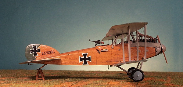
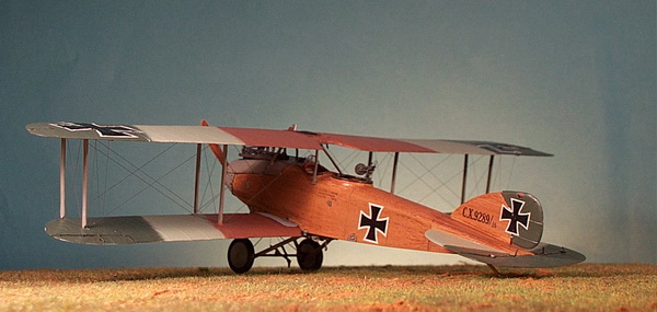
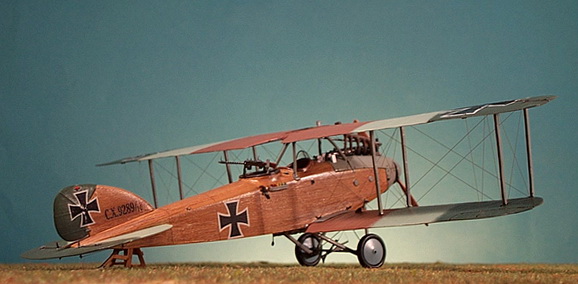
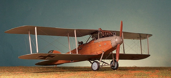
The 1:48 scale WW1 airplane covered in this issue is Jager Miniatures' Albatros C.X, a German two-seater army cooperation aircraft, specifically C.9289/16 of Flieger-Abteilung 18 (abbreviated FA 18). The kit is wholly resin except for a packet of white metal parts, a few injection molded parts, and a generic decal sheet which provides the Eisernes Kreuz markings. The fuselage is cast in one piece with a cut and detail for the cockpit area inserted from below. The floorboard is the bottom piece onto which are attached all of the cockpit items from the kit plus dozens of others to provide added realism. The Albatros C.X was to have been the "Höhenbildflugzeug" (high-altitude photo aircraft) of the Korps and Armee Flieger-Abteilung units but was superseded in the Summer of 1917 by the much better performing Rumpler C.IV. For reasons explained below, however, the Albatros C.X was deployed ahead of the Rumpler C.IV and enjoyed a brief period of success. It was equipped with sophisticated photographic equipment and performed artillery spotting and bombing. All of the equipment used for these missions has to be represented in the model's cockpits, hence, the extensive scratch-building of these items. The fuselage is straight forward with the engine, tail section, tailskid, and landing gear going on first. The cockpit was last because it is difficult to add details once the floorboard is glued in place. The main wings are three pieces for the upper wing and two pieces for the lower wing. All had to be cut according to the kit's instruction since the wings were made for Jager Miniature's Albatros J.I "Infanterieflugzeug". I should note that all struts were re-made by me from flattened brass tubing for added strength. Rigging was completed in .005 monofilament dark gray thread. More construction details and camouflage to follow.
HISTORICAL BACKGROUND
The German High Command (Oberste Heeresleitung or OHL) had come to realize that mobile warfare was no longer possible. In fact, since 1915, the war degraded into positional warfare where both sides faced each other peering over trenches and barbed-wire across a vast and bleak "no-mans" land. Any report of movement along roads and trenches leading up to the front line was an opportunity for an artillery bombardment. German 2-seat C-Type aircraft of 1917 were nearly perfect in their ability to carry out the duties of artillery spotting (Artillerieflug), photo reconnaissance (Photoflug) and ground attack (Bombenflug), among other missions, on a routine basis mostly with light loss to aircraft and crew. A Flieger-Abteilung was assigned to Korps or Army for reconnaissance, artillery spotting, and aerial photography, often referred to as strategic army cooperation. A Flieger-Abteilung-Artillerie, or FA (A), unit was assigned to individual frontline divisions for the same kind of work but for local, tactical purposes.
In February 1917, the German Army withdrew from its untenable Somme positions back to the shorter and more-easily defended Siegfried Stellung which also allowed them to form a reserve. The Allies were caught off guard and advanced only with caution. The area vacated by the Germans was entirely wasted. The strategic withdrawal upset the Allies' planned Spring offensives which were launched nonetheless. On 9 April 1917, the British launched their Arras Offensive against the German 6.Armee and captured Vimy Ridge. On 16 April 1917, the French launched their Aisne Offensive also known as the Chemin des Dames Offensive or Nivelle's Folly which resulted in great loss and a French Mutiny on 1 May 1917. By the middle of May, the British offensive ground to a halt but another assault on 7 June 1917 in Ypres sector seized Messines Ridge, again from the German 6.Armee.
FLIEGER-ABTEILUNG 18 (Later, Lichtbild-Flieger-Abteilung 18)
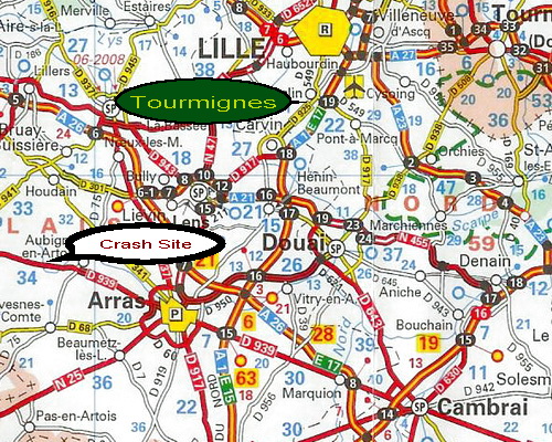
Flieger Abteilung 18, or FA 18, was created as a new unit 11 January 1917 from 3.Kompanie, Flieger-Bataillon Nr. 3 (Darmstadt) per Kogenluft order Nr. 29910 Fl. II. Later, on 10 March 1918 (beyond the scope of this model) it was officially renamed as a Lichtbild strategic photo reconnaissance unit and its title was officially changed to FA 18 Lb although it had been performing in this role already for quite some time. During the Summer of 1917, FA 18 was attached to 6.Armee and probably based at the Flugplatz Tourmignes which is about 20 km south of Lille, 30 km east of Béthune, and 40 km northeast of Arras. Map 1 shows the general area. I have placed the name of Flugplatz Tourmignes south Lille on the map and the approximate area of the crash site slightly northwest of Arras.
|
|
FA 18 operating as the 6.Armee's strategic reconnaissance Abteilung was heavily engaged in penetrating behind Allied lines to obtain photographs and observe rail and road traffic. On 24 April 1917, the crew of Huppertz/Neumiller were lost and made POW. On 1 May, the crew of Hauboldt (KIA)/Kühl (severely injured) crashed at Roubaix. in mid-May 1917 the crew of Mohr (POW)/Dyck (KIA) were shot down in the Savy-Bizet area. On 7 June 1917, the crew of Craatz/Brugger were shotdown and killed near L'Offrande. Then, on 12 July 1917, the crew of Albatros C.X C.9289/17, the subject of this model, were shotdown in the Bully-Savy area. The pilot (Flugzeugfuhrer), Böhm was killed and the observer (Beobachter) Wollenhaupt was captured. For a six-aircraft Abteilung, these were high losses.
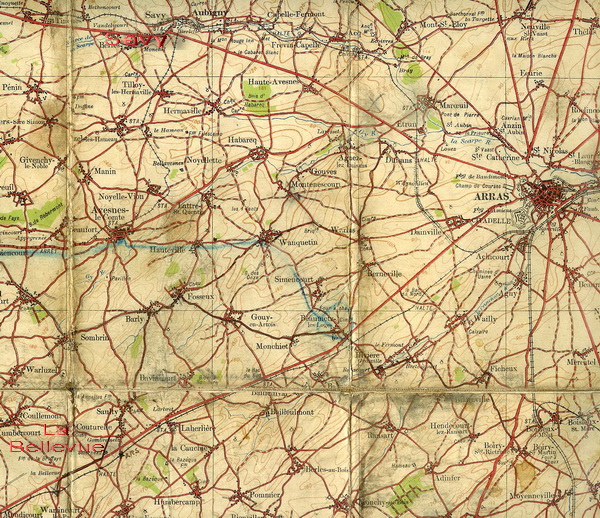
World War I era maps were used to create smaller maps that show pertinent areas relative to FA 18's Albatros C.X C.9289/16. Map 2 shows the Lens-Bully-Savy area. C.9289/16 was brought down in either Savy or Bully (in red on Map 1). Map 3 shows the distant location of the British Aerodrome at La Bellevue (lower left corner) relative to Savy and Arras.
MAP 2
 |
MAP 3
|
|
ALBATROS C.X C.9289/16 RESEARCH
 |
 |
|
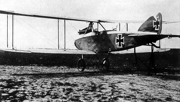
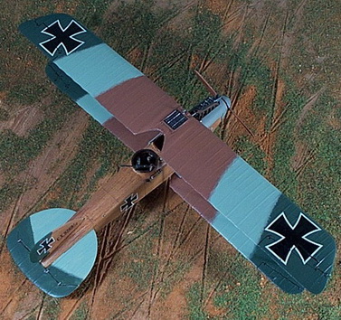
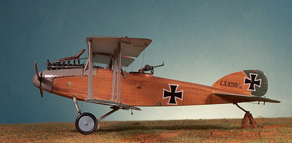
Albatros C.X C.9289/16 undergoing British evaluation left side view does not reveal camouflage pattern. |
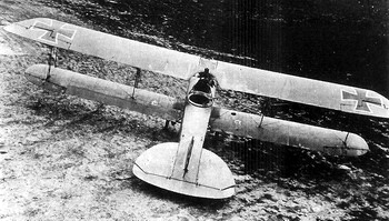
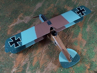
This upper rear view also does not reveal the aircraft's camouflage scheme which I have interpreted to be the three color scheme of late 1916. |
|
Both photos are used with permission of Ray Rimmel of Albatros Productions as it appeared in Windsock Datafile 114 Albatros C.X by Peter M. Grosz, Albatros Productions Ltd, © 2006 |
|
My 1:48 scale model is based on two photographs that appear in Windsock Datafile 112 shown above. This Albatros C.X was from the fourth production order of November 1916 for 100 aircraft (C.9206-9305/16) built by the Ostdeutsche Albatros Werke (OAW) in Schneidemühl, West Pomerania, Germany (renamed Pila, northwestern Poland). By the end of the 19th century the city had become one of the most important railway centers of the region, one of the largest towns in Posen Province, and an important Prussian military city.
The Albatros C.X was powered by 260 hp Mercedes D.IVa in-line engine rated at 260 hp. A total of 400 Albatros C.X aircraft were built in five orders issued by Idflieg from October 1916 to January 1917. Only the first (100) and fourth (100) orders were built by Albatros/OAW. The others were license-built by Luftfährzeug G.m.b.H., (LFG) Berlin-Charlottenburg or LFG Roland (100), Bayerische Flugzeug-Werke A.G. or BFW (50), and Linke und Hofmann Werke A.G., Breslau (100). As of the end of June 1917 in the Frontline inventory, there were 98 Albatros C.X and now 122 Rumpler C.IV two-seat aircraft of which about one third of each were held at Armee Flugparks in reserve. The following table shows the Frontline inventory for all C-Types. Of particular note is the "All Albatros C" summary line which shows a significant decrease in Albatros two-seaters after August 1917. The Albatros C.X in June 1917 accounted for 5% of all C-Types in service.
Frontbestand for Selected German Two-Seaters 1917-18 a
|
Type |
1917 |
1918 |
|||||||||
|
Feb |
Apr |
Jun |
Aug |
Oct |
Dec |
Feb |
Apr |
Jun |
Aug |
Oct |
|
|
Albatros C.I |
52 |
37 |
46 |
13 |
4 |
2 |
0 |
1 |
0 |
1 |
n/a |
|
Albatros C.III |
214 |
174 |
107 |
29 |
15 |
5 |
1 |
1 |
2 |
0 |
n/a |
|
Albatros C.V |
50 |
60 |
57 |
29 |
8 |
5 |
5 |
0 |
0 |
0 |
n/a |
|
Albatros C.VII |
372 |
296 |
165 |
74 |
33 |
11 |
6 |
4 |
0 |
0 |
n/a |
|
Albatros C.X |
0 |
70 |
98 |
47 |
26 |
11 |
4 |
0 |
0 |
0 |
n/a |
|
Albatros C.XII |
0 |
0 |
41 |
93 |
92 |
66 |
48 |
36 |
20 |
15 |
n/a |
|
All Albatros C |
688 |
637 |
514 |
285 |
178 |
100 |
64 |
42 |
22 |
16 |
n/a |
|
AEG C.IV |
90 |
124 |
127 |
63 |
88 |
68 |
40 |
26 |
29 |
34 |
n/a |
|
DFW C.V |
79 |
341 |
839 |
1057 |
901 |
845 |
614 |
665 |
623 |
620 |
n/a |
|
LFG Roland C.II |
53 |
42 |
1 |
1 |
0 |
0 |
0 |
0 |
0 |
0 |
n/a |
|
LVG C.II |
87 |
45 |
20 |
8 |
2 |
3 |
0 |
0 |
0 |
0 |
n/a |
|
LVG C.IV |
58 |
39 |
14 |
1 |
0 |
0 |
0 |
0 |
0 |
0 |
n/a |
|
LVG C.V |
0 |
0 |
0 |
98 |
219 |
446 |
504 |
565 |
312 |
133 |
n/a |
|
LVG C.VI |
0 |
0 |
0 |
0 |
0 |
0 |
0 |
0 |
173 |
400 |
n/a |
|
Rumpler C.I b |
146 |
159 |
217 |
166 |
70 |
21 |
14 |
12 |
2 |
1 |
n/a |
|
Rumpler C.III |
42 |
22 |
15 |
7 |
1 |
1 |
1 |
1 |
0 |
0 |
n/a |
|
Rumpler C.IV c |
0 |
24 |
122 |
257 |
228 |
254 |
222 |
292 |
303 |
300 |
n/a |
|
Sub of Above C |
555 |
796 |
1355 |
1658 |
1509 |
1638 |
1395 |
1561 |
1442 |
1498 |
n/a |
|
Sub Other C d |
318 |
124 |
97 |
118 |
134 |
59 |
16 |
8 |
64 |
96 |
n/a |
|
Total All C Types |
1561 |
1557 |
1966 |
2061 |
1821 |
1797 |
1475 |
1611 |
1528 |
1610 |
n/a |
Frontbestand Notes
| a | Data from WWI Aero volume 107 (for C Types), Dec 1985 |
| b | Includes the Rumpler C.I and C.Ia (Han) |
| c | Includes Rumpler C.IV derivatives (C.V, C.VII, Rubild, etc.) |
| d | All other C Types not listed in this table |
ALBATROS C.X C.9289/16 CAMOUFLAGE COLOR SCHEME
The period up to the Spring of 1916 is referred to as the German "Sky" Camouflage period, basically natural linen finish doped and varnished. The first official camouflage directive was the two-color "dark green and red-brown" scheme ordered by Idflieg in April 1916. It was confusing to both the French and Germans both of whom used essentially the same scheme! After a number of mistaken identify aerial engagements, Idflieg modified its camouflage directive in Summer 1916 and added a third color, light green, sometimes referred to as "light Brunswick green". For years, historians di not note this scheme because dark green and red-brown return almost the same identical tone in black and white photography film used during World War I. However, the demarcation between these two colors is especially evident when the lighter green shade is present only because it forces one to review the photo closely. The production order of which C.9289 was a part was ordered in November 1916 at the height of the three-color period. More than likely, the entire batch was finished as such, possibly into the April 1917 two-color "lilac" period, as I call it. I studied Windsock Datafiles for the Albatros C.VII and C.X and noticed a consistent application of a standard "Albatros" three-color scheme. Albatros varied the scheme in the rudder color, the tailplane angles of camouflage, and the three-color wing pattern. This was possibly a random occurrence on the production line as the rudder sub-assemblies, wing sub-assemblies, and tailplane sub-assemblies all came together on the production line for a specific airframe. It is quite possible that some organized method was actually used but I did not pursue this aspect.
ALBATROS C.X C.9289/16 MARKINGS
This aircraft was not marked other than the Eisernes Kreuz in the traditional eight positions. I used the kit's Eisernes Kreuz markings for the wings, fuselage, and rudder. The Windsock Datafile photo I used as a reference did not reveal the serial number which is normally stenciled onto the vertical fin. I made my own decal for this and for the weight table that only appears on the left side of the fuselage at the pilot's cockpit.
CONSTRUCTION
1) I have relied on Windsock Datafile 114 Albatros C.X by Peter M. Grosz, Windsock Datafile 77 Albatros C.VII by Peter M. Grosz and the kit's drawings for construction details. Note that all of the construction steps have photographs that appear on another of my pages: click here to view.
2) Fuselage Prep: the solid resin cast fuselage eliminates a major construction sub-assembly. Little in the way of cleaning up the casting was necessary. I pre-fitted the engine block and the cockpit floor and required only minor adjustments.
3) Engine Compartment: the engine consists only of a cylinder block to which were added the intake manifolds and spark plug wires. The engine and fuselage cavity were painted a semi-gloss black mixed with a little Vallejo Natural Steel. I lined up the engine according to the drawings in Windsock Datafile 114 and the kit drawings by Martin Digmayer.
4) Cockpit Interiors: the kit did not provide much in the way of cockpit details. The instrument panel was painted in a wood color and augmented with a few switches and gauges which were painted and highlighted then set aside. I added the kit's throttle, magneto, seat, etc. All of this time, the floorboard and the cockpit interior were worked as separate items with several trial fittings to make sure parts added to either did not conflict when assembled. I added observer details including a wireless set, seatbelts, assorted switches, boxes, cables, spare Parabellum drums, and map case. I'm sure I left something out here. After another test fit, the floorboard and cockpits walls were painted in a wood color and properly "grained" and "weathered". Components were painted metallic black or light green-gray.
5) Tail Unit and Tailskid: this comes in five pieces: vertical fin, rudder, left horizontal stabilizer, right horizontal stabilizer, and the elevators as one piece. The horizontal stabilizers were set first, the vertical fin second, the elevators third, and the rudder last. This is always a balancing and alignment art form using super glue. After all of these components of the tail unit were completely dry, I flattened a piece of brass rod for the tailskid. It was bent into shape and some extra two-part epoxy was used to simulate the steel shoe. After this set up, I pre-drilled a hole and glued the tailskid into place.
6) Fuselage Assembly Continued: I checked out the floorboard cockpit assembly one more time and when satisfied that I could do no more that could be seen, I glued it to the fuselage. I applied putty to gaps and, when dry, sanded using 100 grit sand paper, then 150, then 300, and finally, 600.
7) Landing Gear: the kit's landing gear was solid metal and I felt comfortable using it but substituted the axle for a brass rod and added a spreader bar. After dry fitting it in place, I glued it into place making alignment adjustments as necessary.
8) Cabane Trestle: I discarded the kit's cabane trestle parts and made my own from flattened brass rod. I made two U-shaped struts, one for the left side and one for the right side. The bottom of the "U" is the actually the top of the cabane strut and fits into a recess in the center wing panel. It took a lot of fiddling with shape, strut lengths, and strut angles to get a correct but strong trestle. The left and right struts were soldered together. Enough spread allowed for adjusting the widths of the struts to fit the fuselage. Nonetheless, it was a difficult process. This sub-assembly was then glued to the fuselage.
9) Lower Wings: these were prepared to fit to the fuselage by first locating two holes in each wing root to match corresponding holes in the fuselage. I used the drawings to verify the position. I then drilled out the holes, inserted pins, a tested for fit. The wings were not glued into position because the fuselage would have to have its wood grain finish applied first.
10) Propeller: this was supplied in the kit as two individual cast metal blades and a resin spinner. All were cleaned and primed before painting. The blades were glued to the spinner. Again, great care was taken for alignment and pitch. The base color of the blades is light ochre with dark brown laminations. Colored pencils were used to create striations in the "wood" and then they were hand-rubbed. The colored pencil wax and natural oil from the fingers help distribute and blend the colors into a nice finish. I added more or less of a shade or two to get the final effect. The spinner was painted light gray-green
11) Fuselage and Fin Wood Grain Finish: when it came time to paint the fuselage, it became apparent that the landing gear and the tail unit were in the way but I left them on and began by painting a base coat of light ochre. I let this dry for 24 hours. The wood grain is done in the same manner as with the propeller using a variety of colors to simulate wood grain with a lot of finger rubbing between colors. Each color is applied as a streak using a sharp colored pencil. It took about a half hour to complete the finish. The hand-rubbing left a realistic satin finish.
12) Painting the Fuselage: I will let the photo below speak for the finish except to explain a few features not covered. The wire coming from the rear of the engine is solder wire that will hook up to the wing radiator. Note the pins for the lower wings. This is when I decided to apply decals. I used the kit's Eisernes Kreuz decals but made the weight table and serial number using clear decal paper and my inkjet printer. Note also the control horns on the tail unit. I used heavier gauge steel piano wire for the landing gear to prevent side movement. The light color on the tail plane is Misterkit Albatros Light Green and the dark color is Misterkit Albatros Dark Green. Paint color chart is at the end of this article.
%20Alb%20C.X%2010.jpg)
13) Upper Wing Assembly: the upper wing consists of two outer wings joined by a center section. However, the outer wing panels had to be cut slightly since they were designed for use in the Jager Albatros J.I kit which had a slight swept-back upper wing. This was easy to do by simply squaring up the ends of each outer section where they will join the center section. The three pieces were all pinned with small diameter brass rod for strength. Once the super glue was completely dry, I used ordinary hobby filler for the gaps. After that dried, I used various grades of sandpaper to finish. The holes for the wing struts were drilled out for a better fit. Also, holes for the rigging wire were drilled but carefully so as not to go through the wing; some did anyway but I left them to be filled later.
14) Lower Wings: these were also drilled for struts. Rigging holes were drilled through the wing so that rigging wire can pass through, be glued, and then cut off. The wings were glued to the fuselage and carefully aligned on the brass pins.
14) Wing Struts: The kit's struts were not used. Instead, I made my own from flattened brass tubing with a smaller brass rod at either end. The struts have to be cut exactly the same or you will have bulging in the wings and end up with a poor fit.
15) More Wing Work: I painted the underside of the upper wing with one coat of Albatros Light Blue. When dry, I glued one piece of monofilament rigging wire into each rigging hole leaving it long enough to easily reach its corresponding hole in the lower wing. They wing struts were now glued to the lower wing and carefully allowed to dry in a vertical position. They were painted with a primer when set. I painted the upper side of the lower wings in one coat each of the camouflage colors according to the scheme I chose. Now, with the upper wing with its dozens of dangling rigging wires, I glued it to the trestle and the inboard wing struts. When dry, I glued it to the outboard struts. Of course, alignment was critical but the small pins at the end of each strut help secure the wings. When dry, the radiator pipe was connected to a pre-drilled hole on the underside of the wing-mounted radiator. Aileron wires were made from fine piano wire glued one at a time into place.
16) Rigging Wires: I saved rigging the control wires to last because on earlier models they went in at the time the tail unit was built and subsequently got knocked around. I like the PE control horns from Eduard but have to drill out the holes a bit to take the .005 monofilament thread. Wing rigging was now fairly easy. Starting from the inside, I took a dangling wire on the upper wing, passed it through its corresponding member in the lower wing, attached an alligator clip to the end for weight, and placed a drop of super glue in the hole on the underside of the lower wing. I usually do four at a time and flip the model over right-side up and let the wires dangle with the weight of the alligator clip holding them taut in the rigging hole. When dry, I remove the clip and cut them flush with a sharp X-Acto blade. For the Albatros C.X there were 32 wing strut wires, 6 aileron wires, 2 drift wires, 2 landing gear wires, and 4 elevator control wires. That's a total of 46 wires.
17) Details Added (or not): When researching a model to build, I start a list of details that I think should be added that are not always present in the kit - propeller decals (none supplied and none found on photos of this aircraft); struts painted light gray-green (done); flare pistol and flare cartridge rack (mounted on the starboard side); radiator shutter linkage (not visible in photos so not added); bomb brackets (added to front and rear of each under slung bomb); weighted wireless antenna added; claw brake detail added including hand-made coil spring and wires; minor engine detail; small radiator expansion tank to top wing; windscreen (see below); detail of Parabellum machine gun including mount and takeoff/landing securing bracket; Spandau front machine gun sights (none seen in any photo!); wing compass detail; radiator lines in and out; nameplate (didn't see any on Albatros or OAW-built aircraft); landing gear strut step on port side; wing walks painted light gray-green; couldn't verify location of a fuel tank breather cap; step port side for observer; rigging packet (decided not to add it); gun ring handle added.
18) Windscreen: I always manage to forget the windscreen which should be glued in place before the upper wing goes on. I managed to get in place. It was a scratch-built piece of clear plastic from a grocery store vegetable container. I literally guessed at the curvature of the fuselage and the arc of the windscreen.
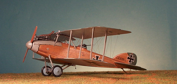
16) Final Painting: The upper surfaces were painted in a three-color scheme of dark green, red-brown, and light green. I used the Misterkit range of paints as noted in the table below. As explained above, I used the probable scheme for this Albatros C.X because I could not see the demarcation of colors on the one overhead shot of this aircraft. The fuselage was plywood covered and varnished. I described above how I interpreted the finish using colored pencils. The underside of the wings and tail unit were painted in Misterkit Albatros Pale Blue. The Albatros C.X had a number of metal parts such as the spinner, cowling, engine access panels, and struts and these were painted light gray-green which was specially formulated for metal and differed from the dope used on canvas and the varnish used on wood. Except for the bit of wood color for the propeller, floorboard in the cockpit, and tailskid, there are no other colors except a dark brown for the cockpit coaming and dark gray for the tires. The entire model was oversprayed with a satin polyurethane. This seals the paint and gives the aircraft a more realistic doped finish. It is absolutely necessary to do this before applying decals.
PAINT COLOR SWATCHES USED ON THE ALBATROS C.X
 |
Misterkit MKGC05 Albatros Dark Green |
 |
Misterkit MKGC01 Albatros Red Brown |
 |
Misterkit MKGC01 Albatros Pale Green |
 |
Misterkit MKGC03 Albatros Pale Blue |
 |
Vallejo Acrylic Mix of VC0907 (Light Pale Blue Grey), VC0885 (Pastel Green), and VC0866 (Grey Green) |
 |
Andrea ANXC18 Slate Grey (for the tires) |
ALBATROS C.X C.9289/16 FINISHED PHOTO GALLERY
SPECIAL THANKS TO RAY RIMELL OF ALBATROS PUBLICATION AND THE PETER M. GROSZ COLLECTION
------------------------------------------------------------------------------------
BIBLIOGRAPHY
WWI Aero, volume 107 (for C Types), Dec 1985
Flanagan, Brian P. The Great War 1914-1918 - Chronology of Events of World War I: Cross and Cockade (US), Volume 7, No.2, pages 200-204.
Fliegertruppe website 21 Feb 2009, www.fliegertruppe.de
Frank, Norman; Bailey, Frank; and Duiven, Rick. Casualties of the German Air Service 1914-1920. London: Grub Street, 1999.
Grosz, Peter M. Windsock Datafile 77 Albatros C.VII. Berkhamsted, Hertfordshire, UK: Albatros Publications, Ltd., 1999.
Grosz, Peter M. Windsock Datafile 112 Albatros C.X. Berkhamsted, Hertfordshire, UK: Albatros Publications, Ltd., 2006.
G.S.G.S., OSO. Lens, France, Map Scale 1:100,000. 1915.
Shores, Christopher; Franks, Norman; Guest, Russell. Above the Trenches. A Complete Record of the Fighter Aces and Units of the British Empire Forces 1915-1920. London: Grub Street, 1990.
|
|
|
Eduard 1:48 Aviation Militaire de France Pilot Officer in Overcoat |
GO TO?
.jpg)