|
ISSUE NUMBER 4 |
HISTORICAL MINIATURES BY GEORGE GRASSE |
MAY 2009 |
HISTORICAL MINIATURES JOURNAL ISSUE NUMBER 4
BY GEORGE GRASSE
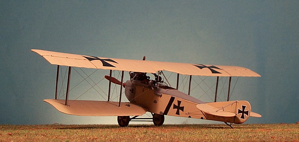
BUILDING THE COPPER STATE MODELS 1:48 SCALE GERMAN AVIATIK C.I
PURPOSE
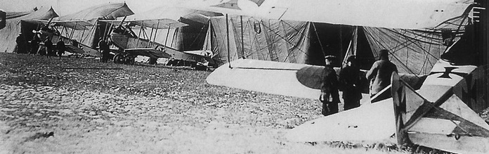
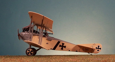
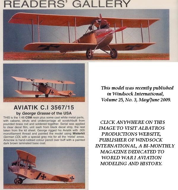
This issue's 1:48 scale WW1 airplane is Copper State's Aviatik C.I two-seater army cooperation aircraft, specifically C.3562/15 of Artillerie Feldflieger Abteilung 207 (abbreviated AFA 207 or FFA(A) 207). It is based on one photograph that appears in Windsock Datafile 63 shown below. C.3562/15 is the middle aircraft parked alongside another Aviatik C.I. An Albatros C.I is on the right. More about this photo and C.3562/15 later on.1
 |
|
This photo is used with the kind permission by Ray Rimmel of Albatros Productions as it appeared in Windsock Datafile 63 Aviatik C.I by Peter M. Grosz, Albatros Productions Ltd, © 2007 |
The kit is wholly resin except for a packet of white metal parts, a small photo-etch sheet, and decals which can be used to finish two different aircraft, both trainers. This is a four-sided fuselage and has to be aligned with precision so the formers are square. Otherwise, many of the interior parts will be off center, the rear top deck won't fit properly , and the nose will not come together cleanly. The detail is quite good especially the subtle "canvas" covering of the fuselage aft of the metal cowling. The interior detail is quite impressive with formers, fuel tanks, bomb chutes, and much more. You get a feel for the design and construction of the period. Upper wing is one piece, lower wing is two pieces, tail is four three pieces. Other resin parts include the upright exhaust manifold, radiator, and wheels. Metal parts include the engine, propeller, struts, and landing gear. Lots of drawings but not so easily interpreted. I discarded all of the resin and metal wing struts, cabane trestle struts, landing gear, and tail braces. Instead, I made my own with flattened brass tubing with small brass rods protruding from both ends. More on that later. Rigging is my first attempt at .005 monofilament thread (MFT). More information is provided in the construction section below. Since I am strictly a two-seater builder, I would like to see more of them especially the pre-war, first-generation Albatros, Aviatik, and LVG B-types.
HISTORICAL BACKGROUND
The Germany High Command (Oberste Heeresleitung or OHL) expected that the great offensive on the Verdun front beginning in February 1916 would be the decisive battle. It was expected that the great offensive would consume French reserves by drawing them away from Flanders where, it was hoped, the British would be isolated, split off from the French, and driven to the Channel and out of the war. Verdun would be overrun and the two victorious wings of the German Army would converge on Paris. Verdun proved to be a costly campaign for both sides. So much was the German pressure at Verdun, the French finally impressed the British to plan and launch their own great offensive on the Somme Front. This relatively quiet sector was the operational area for FAA(A) 207 where it conducted the usual army cooperation duties related to artillery spotting and local reconnaissance, its specialty.
Battle OF THE SOMME
The Summer of 1916 was punctuated by the Allied offensive on the Somme beginning on 1 July 1916 and its purpose was to relieve pressure on the Verdun Front which, since February 1916, had already caused hundreds of thousands of casualties on both sides without material gain for either. Even though the German Army possessed interior lines between the Somme and the Verdun Fronts, it took several weeks for reinforcing units on in other areas to disengage, move, and get into the Somme area. Initially outnumbered, German reinforcing infantry, artillery, and air units begin arriving by 7 July. The German second line of defense was breached by 14 July and German air defense was nearly non-existent. By 19 July, the aviation strength of the German 1st Armee on the Somme was substantially reinforced by 164 aircraft but the odds were still in the neighborhood of 2:1 in favor of the Allies. The one mitigating factor in stemming the tide for Germany in the air was the aggressive use of the Fokker Eindecker scouts and the vulnerability of Allied aircraft especially the woeful BE.2 series. Allied reconnaissance and artillery spotting sorties were consistently shot down while German army cooperation aircraft were beginning to gain uninterrupted time over the Allied lines. In this setting FAA(A) 207 must have been very busy.
FELDFLIEGER ABTEILUNG (ARTILLERIE) 207
Feldflieger Abteilung (Artillerie) 207 was created by KM (Preußischen Kriegsministerium) Nr. 828/10.15 A7L 23 October 1915 and was mobilized on 10 November 1915.3 On 1 December 1916 by order of KM Nr. 1145/16g A7L it was renamed Flieger Abteilung (Artillerie) 207, FA(A) 207. Note the distinction between FFA(A) 207 and FA(A) 207. The transition was a significant event in German military aviation because it placed a general officer in command of the German Air Service (Kogenluft der Luftstreitkräfte), increased the establishment of artillery flights from 4 to 6 aircraft, and increased the number of these flights so that every German frontline infantry division would have an artillery flight available to direct artillery fire. Of course, many other innovations occurred at this time but that is another topic. Getting back to the older formation, FAA(A) 207, I consulted Casualties of the German Air Service 1914-19206 looking in both the KIA and non-KIA entries for this unit up to the time it was renamed. As a new artillery spotting unit formed in late 1915, it may have been sent initially to the Somme Front before the Allied offensive. I found two entries for FFA(A) 207, as follows:
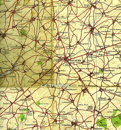
28 August 1916, Ltn Böhme (observer) WIA lightly near Le Transloy. My World War I Lens sector map4 showed that Le Transloy was about 5 km southeast of Bapaume in the Somme sector. I could not find a corresponding KIA entry for the pilot so I initially thought he was unhurt. To confirm the casualty, I checked British victory claims for that date. I searched alphabetically and the first name for that date was Albert Ball. He shot down three that day all in the Bapaume sector all of which were LFG Roland C.II "Walfisch" aircraft. One entry had an interesting footnote: "Ltn Joachim von Arnim and Ltn Böhne [sic], Ft Abt 207, pilot killed, ob [observer] landed a/c Nr [near] Transloy." So, the pilot was KIA and I checked his name in that section and found that he was listed as a pilot in Jasta 2. Apparently, as a member of FAA(A) 207, he was selected to become a fighter pilot but was killed on this date before he could be transferred. This confirms the location of FAA(A) 207 as being in the Somme sector on 28 August 1916 and must have been flying LFG Roland C.II aircraft as part of their complement.6
10 September 1916, Ltn Karl Trilling (O) KIA near Damloup: I checked Damloup on an internet satellite map and found two sites close to each other. One was Vaux-devant-Damloup and the other was Damloup both in the Verdun sector. It seems that FAA(A) 207 was sent to this sector sometime between 28 August and 10 September 1916.
I felt comfortably sure that FAA(A) 207 was in the Somme sector in Summer 1916 but I don't yet know their aerodrome or the actual crew of Aviatik C.I C.3567/15. At any rate, I had enough information to be somewhat historically accurate in portraying my model.
SUMMARY OF FAA(A) 207 SIGNIFICANT DATES
| Created | 23 October 1915 |
| Mobilized | 10 November 1915 |
| Somme Casualty | 28 August 1916 |
| Verdun Casualty | 10 September 1916 |
| Renamed FA(A) 207 | 1 December 1916 |
AVIATIK C.I C.3562/15 RESEARCH
 |
|
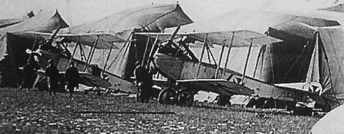
The photo above is from the Peter M. Grosz collection and used with permission of Albatros Publications. It is a close-up from the original photo on page 7 of Windsock Datafile 63 showing two Aviatik C.I aircraft of Artillerie Feldflieger Abteilung 207 (site and date not known, probably Summer 1916, Somme Front). The nearest aircraft is C.3562/15, the subject of this article. |
This Aviatik C.I aircraft was from the sixth production order of November 1915 for 75 aircraft with serial numbers C.3500-3574/15. It was powered by either a Benz Bz.III rated at 150 hp or a Mercedes D.III rated at 160 hp. A total of 402 were built by the parent Aviatik and a further 146 were built under license by Hannover for a grand total 548 machines. One of the Aviatik-built aircraft was designated "C.Ia" with modifications. It served as a prototype for the Aviatik C.III series.5 These aircraft were issued to Feldflieger Abteilungen (FFA), FFA(A), and Kasta units to carry out two-seater army cooperation duties, e.g., reconnaissance, photography, and artillery spotting. In the case of the "bomber" Kastas, bombing was intended but more often than not these units flew Speerflug or "barrier flights" which were intended to prevent Allied army cooperation and bombing aircraft from penetrating into German rear areas especially during the great Verdun campaign in the first half of 1916. Often, Aviatik C.I and other German two-seaters would fly adjacent to or get behind the vulnerable French two-seat pusher Voisin bombers and shoot them down. Aircraft assigned to FFA(A) flights performed army cooperation duties especially artillery spotting (Artillerieflug) and local reconnaissance (Probeflug or Naherkundungsflug).
I believe the photo was taken on the Somme Front in early Summer before FAA(A) 207 received one or more LFG Roland C.II "Walfisch" two-seaters.
CONSTRUCTION
1) I have relied on Windsock Datafile 63 Aviatik C.I by Peter M. Grosz1 , German Aircraft of the First World War by Gray & Thetford7, and the kit's drawings for construction details.
2) Fuselage Prep: The fuselage is tricky because you have to manipulate, align, and glue two fuselage sides and the bottom all the while making sure the turtle deck and cockpit/engine deck will fit properly. When the sides and bottom are glued, I attached the turtle deck, again, making sure the cockpit/engine deck and the nose cowling piece would fit later. When all of these pieces are fixed in place they make up the basic fuselage. I can't overemphasize that if you are off in the slightest, major problems will occur.
3) Tail Unit: This includes the one-piece horizontal tail plane, the vertical stabilizer, the rudder, supporting braces, the tailskid, and control horns and wires. From the front of the aircraft, the tailplane has to be squared up while the glue sets. I drilled out holes for the small diameter brass support braces I used instead of the kit supplied PE parts which are too flimsy for me. I constructed a brass tailskid as well using a V-shaped piece soldered to the skid for support. I drilled out the control wire holes in the fuselage and in the top of the horizontal stabilizer which serves as a "pass-through" for the upper elevator wires. I used .005 MFT in charcoal color. I glued one end into the pre-drilled fuselage openings, waited for them to dry, and passed the other end through the PE horns and tied them off. A drop of super glue secured them and I cut off the excess.
3) Engine Compartment: The engine is built up first. It is a pre-packaged Copper State (CS0126) 160 hp Mercedes D.III engine in white metal in five pieces excluding the exhaust collector. This compartment and the crew compartment have a number of PE bulkheads all of which were installed at this time using the Copper State detail drawing. In the engine compartment, the oil tank was installed first, then the engine itself. Again, careful alignment and fit are important especially with regard to the engine/cockpit deck that will fit over the top.
4) Cockpit Interiors: Additional components were now added working my way back from the engine. This included the two fuel tanks on either side of the observer's cockpit, his bench and the pilot's seat, the bomb tubes (made from plastic tubing), the control column, steering wheel, and a scratch-built instrument panel using a number of the kit supplied instruments from their pre-packaged Copper State (CS0122) German Gauge Set. I scratch-built seat belts for both crew members and a number of miscellaneous boxes and panels with appropriate wiring. Some of these details were pre-painted but all of the other interior details were now painted.
4) Fuselage Assembly Continued: With the cockpits detailed, I had to soak the engine/cockpit top deck in hot water and bend the resin to better fit the contour of the fuselage sides. This piece was then glued in place. The nose cowling was glued. I reviewed all joints and added a bit of filler here and there to seal it up. Careful sanding to remove excess filler followed. The forward fuselage sides have a PE panel that corresponds to Aviatik-built C.I aircraft. This was fitted and then glued in place.
5) Landing Gear: The kit's landing gear struts were discarded and I made to V-struts by nipping and bending at the apex. I selected the appropriate brass rod for the axle and soldered that to the two landing gear V-struts. I made a reinforcing strut based on the drawings from another piece of brass rod. There is an oddly-shaped plate near the apex of the V-struts which I made from plastic stock. Music wire of .009 diameter was used to reinforce the landing gear. The wheels covers were pre-painted clear doped linen (CDL) with medium gray tires and then glued to the axles.
6) Cabane Trestle: I discarded the kit's cabane trestle parts and made my own from brass rod. I first made two V-struts and soldered a longitudinal bar at the top to secure the structure. This sub-assembly was then glued to the fuselage. At this point, I made up a number of small twisted copper fuse wire "turnbuckles" and drilled holes near the wing root. The turnbuckles were glued in place and with a small eyelet, would facilitate rigging later on.
7) Lower Wings: The location for the lower wings was matched to the kit's drawings and the Windsock Datafile drawings. I carefully marked off two locations and drilled matching holes in the fuselage and the wing roots. I added the PE wing walks to each wing and, after careful fitting, I glued the wings in place taking care to align them with the tail plane.
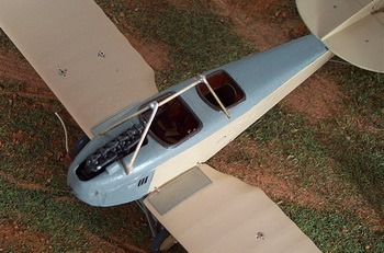
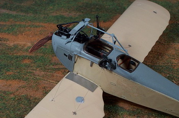
8) Painting: The fuselage, tail unit, and wings were painted CDL overall. The top decking, forward side panels, landing gear sub-assembly, and tail unit braces were painted light gray. Here are a couple of photos showing progress to this point.

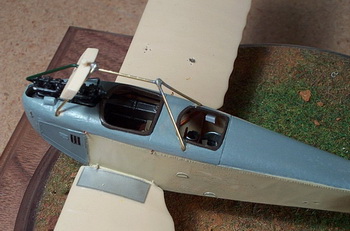
9) Radiator: I pre-drilled to holes in the radiator for the "in and out" radiator pipes. The radiator was glued to the front cabane trestle. When dry I measured a piece of brass rod for the radiator pipe that passes over the engine. After try-and-error cutting and bending, this was glued in place. I used solder wire for the other line. I added four more "turnbuckles" just below the observer's cockpit. See photos below.
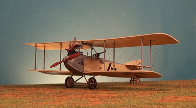
10) Propeller: It was painted a light ochre or buff color. The laminations were painted in a dark brown. Colored pencils were used to create striations in the "wood" and then they were hand-rubbed. The colored pencil wax and natural oil from the fingers help distribute and blend the colors into a nice finish. I added more or less of a shade or two to get the final effect.
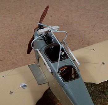
11) Parabellum Machine Gun Rails and More Detail: I discarded the kit's PE parts that would have made the gun rails. These didn't seem stout enough so I made my own out of brass rod including the fuselage supports. I assembled the machine guns using the resin parts and the PE slotted barrel covers. Next, I fashioned the wire guard rails out of thin brass rod and attached them to the forward cabane trestle struts. These guards prevented the gunner from firing into the propeller arc. I painted a compass in the compass well and made a cover from sheet lead. A mirror was attached to the apex of the rear cabane trestle for the pilot. I ran four rigging wires to the observer's turnbuckles. The photos below shown the completed work primed and the completed work finished with machine guns on the right.
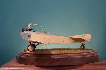
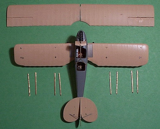
12) Wing Struts: You've heard this before, "I discarded. . . " and in this case I discarded the white metal struts and made my own from flattened brass tubing with a smaller brass rod at either end. If you work carefully, the flattening process goes quickly and comes out cleanly. The tedious part was cutting each strut to exact length. Here's a photo of the model just before attaching the upper wing.
13) Upper Wings: First, I glued pieces of MFT into each rigging hole in the underside of the upper wing. Make sure you paint the underside first! I glued each of the struts to the lower wing making sure they were perpendicular. I figure that a few will pop out during upper wing assembly but for now I need them in place because I will need both hands to secure the upper wing during the gluing process. I placed glue onto the tip of the four inboard struts and the trestle and likewise in the corresponding holes in the upper wing. I set the upper wing on the trestle and maneuvered the four struts into position. I set the model down carefully on its landing gear and "eyeballed" for alignment making slight adjustment to the wings. When thoroughly dry, I glued the outboard struts in place.
14) Rigging: This was delightfully easy to do. I used to use music wire and had to cut each piece and trial fit. All I had to do here is push an MFT piece through its proper rigging hole in the lower wing, put a tiny amount of super glue in the hole, let it dry, then trim it off. As you recall, four of the observer's turnbuckles were already connected to the lower wing. The four turnbuckles in the wing roots had their MFT wires pulled through, looped, tied, glued, and trimmed. It was quick compared to music wire.
15) Windscreen: This should have been down at an earlier stage but I was able to configure a windscreen from thin, clear plastic material used in vegetable and fruit containers.
16) Final Painting: This last step involved the wings which should have been pre-painted. First, however, I had to fill all rigging holes, sand them down, and buff the resin surface carefully with fine, black sandpaper. The CDL finish was a simple two coat application with brush.
Additional construction photos can be found here: Aviatik C.I Construction Article
AVIATIK C.I C.3562/15 COLORS
Aviatik C.I aircraft were plainly finished in CDL which is really a process of brushing onto the fabric several coats of clear dope. Usually one and sometimes two coats of clear varnish were applied as a final sealant. The overall effect was a pale beige-yellow that weathered to a slightly darker shade with time and exposure. I'm not convinced that there was a systematic application of white, gray, or sky blue pigments into this process. In fact, if it ever was done, it was a local "paint job", in my opinion. This period up to the Spring of 1916 is referred to as the German "Sky" Camouflage period and all manner of theories have been advanced to prove that an intentional pigmented scheme was in effect. Not surprisingly, no documentation has been uncovered to prove that case other than the photo interpretation by current historians. The two-color "dark green and red-brown" scheme was ordered by Idflieg in April 1916 but I have not seen any photos of Aviatik C.I aircraft in a camouflage scheme. Some photos suggest an overall darker color than CDL but the vagaries of WWI photography make it impossible to determine the true shade. I used Misterkit MKGC10 CDL.
All metal parts were painted light gray and I used a mix of colors described in the chart below. This light gray paint was formulated for metal and applied universally by all manufacturers and probably varied in shades and hue widely. It is sometimes referred to as a "light green-gray" implying a hint of green in the gray and that may well have been true. I have added a trace of "green" to my mix. Except for the bit of wood color for the propeller, floorboard in the cockpit, and tailskid, there are no other colors. The entire model was oversprayed with a satin polyurethane. This seals the paint and gives the aircraft a more realistic doped finish. It is absolutely necessary to do this before applying decals.
PAINT COLOR SWATCHES USED ON THE AVIATIK C.I
|
|
Misterkit MKGC10 Clear Doped Linen |
 |
Vallejo Acrylic Mix of VC0907 (Light Pale Blue Grey), VC0885 (Pastel Green), and VC0866 (Grey Green) |
 |
Andrea ANXC18 Slate Grey (for the tires) |
AVIATIK C.I C.3562/15 MARKINGS
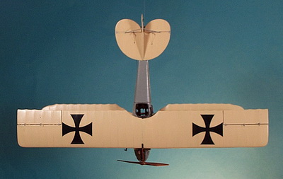
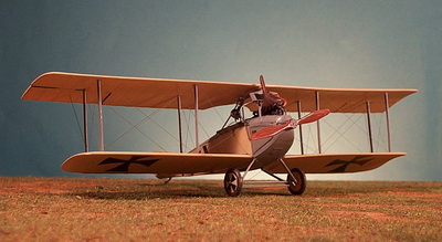
I used the kit's Eisernes Kreuz markings for the wings, fuselage, and rudder. Applying the decal to the wheel covers was a problem and I just painted them myself. The black diagonal stripe forward of the fuselage cross was cut from a stock piece of black decal sheet, trimmed, fitted, then applied. The Windsock Datafile photo I used as a reference suggests that another but smaller marking was forward of the black diagonal stripe and may have been an aircraft number but I couldn't really make it out. The serial number was a decal that I made. I hand painted the Aviatik nameplate that appears on both sides of the engine side panels. I also painted the "hand holds" in black that appear on the rear bottom of the fuselage sides. I couldn't tell from photos what the color of the "wing walks" was to be so I painted them the ubiquitous light gray.
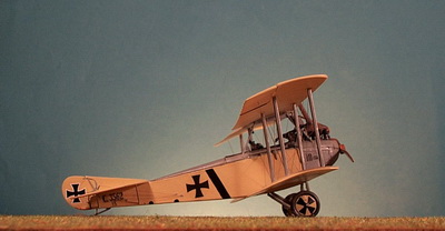
FINISHED PHOTO GALLERY

SPECIAL THANKS TO RAY RIMELL OF ALBATROS PUBLICATION AND THE PETER M. GROSZ COLLECTION
ADDENDUM: 25 June 2009
------------------------------------------------------------------------------------
END NOTES AND BIBLIOGRAPHY
1 Peter M. Gross, Windsock Datafile 63 Aviatik C.I. Berkhamsted, Hertfordshire, UK: Albatros Publications, Ltd., 1997.
2 Brian P. Flanagan, The Great War 1914-1918 - Chronology of Events of World War I: Cross and Cockade (US), Volume 7, No.2, pages 200-204.
3 Fliegertruppe website 21 Feb 2009, www.fliegertruppe.de
4 Lens, France, scale 1:100,000. G.S.G.S., OSO 1915.
5 Peter M. Gross, op. cit.
6 Norman Franks, Frank Bailey, and Rick Duiven. Casualties of the German Air Service 1914-1920. London: Grub Street, 1999.
7 Peter Gray and Owen Thetford. German Aircraft of the First World War. London: Putnam & Company Ltd, 1962.
|
|
|
Czech Master Resin 1:48 Luftstreitkräfte Pilot in Leather Flying Jacket |
GO TO?
.jpg)