
|
ISSUE NUMBER 3 |
HISTORICAL MINIATURES BY GEORGE GRASSE |
FEBRUARY 2009 |
HISTORICAL MINIATURES JOURNAL ISSUE NUMBER 3
BY GEORGE GRASSE
BUILDING PLANET MODELS 1:48 SCALE GERMAN RUMPLER C.IV

PURPOSE
This issue's 1:48 scale WW1 airplane is Planet Model's 1:48 Rumpler C.IV two-seater army cooperation aircraft. Specifically, it represents C.8340/17 flown by Flieger Abteilung 48b (FA 48b) in the period September through November 1917 from the Tourhout Flugplatz in Flanders. The model is based on two photographs and a color profile by Walter Werner appearing in Das Propellerblatt Nummer E2, 2007. This Rumpler C.IV was part of a stable of six aircraft flown by FA 48b which, at this time, included Hannover CL.II C.9210/17, LVG C.V C.3244/17, LVG C.VI C.9413/17, LVG C.VI 9435/17 and one other aircraft, probably another DFW C.V. Different crews flew these aircraft at different times depending on the mission but at least on two occasions in this time period a Rumpler C.IV (serial unknown) was flown by Uffz. Otto Semar (P) and Ltn d R Otto Willie (O).
The kit is wholly resin except for a small packet of plastic struts intended for strength. It is a modified version of Planet Model's Rumpler C.I which included a photo-etch sheet for details: strangely, this kit does not. The fuselage is in two halves with cockpit floorboard, some basic cockpit details (seat, bench, control wheel but little else). Upper wing is one piece, lower wing is two pieces, tail is three pieces. Other resin pieces include engine, intake manifold, exhaust stack, wing- mounted radiator, propeller, and wheels. I discarded all of the wing struts, cabane trestle struts, landing gear, and tail braces. Instead, I made my own with flattened brass tubing or rod. Rigging is .007 music wire. More information is provided in the construction section below.
HISTORICAL BACKGROUND
The Rumpler C.IV is generally referred to as a third-generation C Class aircraft intended to perform high-altitude, long-range reconnaissance missions for the Flieger Abteilungen which were generally assigned to army and corps headquarters. Local reconnaissance, artillery spotting, and low-level ground attack were assigned to Flieger Abteilungen (Artillerie) units, abbreviated FA(A), attached directly to specific front line divisions. The Rumpler C.IV met the Idflieg specifications issued in the Fall of 1916 for a high-performance aircraft that could carry the newly developed Reihenbildkamera (film strip camera, literally "strip photo camera"), that could automatically take consecutive photographs of enemy rear areas and have the developed photos (bilden) assembled in a continuous mosaic. In every case, the aircraft operated at altitudes exceeding 6000 meters to which enemy fighters could only reach except in rare circumstances (e.g., McCudden's "souped-up" SE.5a).
By late 1916 the current high-altitude reconnaissance machine in service was the Albatros C.VII powered by a Mercedes D.IV engine rated at 220 hp. Two aircraft were chosen for further development as replacement for the under-performing Albatros C.VII in late 1916. One was the Albatros C.X and the other was the Rumpler C.IV, both of which were to be fitted with the Mercedes D.IVa engine rated at 260 hp. Other engines were becoming available but the Mercedes was the current favorite and especially liked by ground crews. Production began in September 1916, and these were rolling off the lines by November and December.
Both aircraft models were at the front undergoing combat testing by early 1917. Albatros C.X results were somewhat disappointing, being little better than the Albatros C.VII already in service. However, the Rumpler C.IV, which met performance expectations, suffered from fuselage structural problems that seriously delayed production. In fact, all Rumpler C.III (only a few built) and all Rumpler C.IV aircraft in the field were returned to the factory for rear fuselage strengthening plus those C.IV airframes then on the production line; the modifications were made from March through April of 1917. Meanwhile, Albatros was able to produce a number of C.X aircraft of which only the fourth batch of 100 ordered in November 1916 were deployed to front-line units. Finally, in May the first of the modified Rumpler C.IVs were being issued from the Flugparken. The Albatros C.X of the fourth production batch were allowed to "die out" at the front but many were turned in for the Rumpler C.IV and all but disappeared to advanced training units by the end of December 1917. The Rumpler C.IV soldiered on and became the foundation for a number of specialized versions that served in the high altitude reconnaissance role through the end of the war.1
Third Battle of Ypres
The Third Battle of Ypres was fought from June to November 1917 and covered that part of Flanders in Belgium bordered by Forêt d' Houthulst in the north and the woods west of Zandvoorde near the canal in the south. This grand battle produced a number of famous place names: Inverness Copse, Messines Ridge, Passchendaele, and Polygon Wood, to name a few. It is also the setting in which FA 48b performed nearly all of its missions during the Summer and Fall of 1917. It was based at Tourhout Flugplatz in Flanders southeast of Brugge, Belgium, which it shared for a time with Schutzstaffel (Schusta) 26b. During the battle from the book, Casualties of the German Air Service 1914-1920,3 I found four dates on which members of FA 48b were killed or wounded in action representing at least four aircraft probably lost.
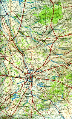
FLIEGER ABTEILUNG 48b
Flieger Abteilung 48b (FA 48b) was created on 11 January 1917 from Feldflieger Abteilung 6b (FAA 6b). From the beginning of the war to the Fall of 1916, the German air service was known as Fliegertruppen (Aviation Troops). A "radical reorganization" occurred in November 1916 and the name was changed to Luftstreitkräfte, meaning air force. All of the existing reconnaissance formations were reorganized and renamed. The existing Feldflieger Abteilungen (FAA) were redesignated Flieger Abteilungen (FA) and the existing Artillerie Feldflieger Abteilungen, abbreviated either AFA or FAA(A), were redesignated Flieger Abteilungen (Artillerie) or FA(A).2 However, it should be noted that these were not just title changes, say, from FFA 1 to FA 1. In fact, FFA 1 was redesignated as FA(A) 276, for example. In general, FA units performed "strategic" army and corps cooperation missions while FA(A) units performed "tactical" or frontline division cooperation missions, especially artillery spotting and ground support. A good source that covers the evolution of the German Air Service is Ian Sumner's German Air Forces 1914 -185.
Unteroffizier (Uffz) Otto Semar joined the unit in early September 1917 as a Flugzeugführer (pilot). He kept a diary which appeared in Das Propellerblatt, Nummer E2, 2007, which I translated to get the information I needed for research on Rumpler C.IV C.8340/17. Specifically, his diary for the period September to November 1918 was most relevant. He began flying the abteilung's different aircraft on a variety of missions in Ypres sector encountering all of the hazards including ground fire, weather, and enemy aircraft. His "Beobachter" (observer and aircraft commander) was Leutnant der Reserve Otto Wille. When the southern end of the Forêt d' Houthulst was taken by the Allies, FA 48b moved some or all of its aircraft to an unspecified aerodrome nearer Brugge. Aircraft specifically flown by Semar are listed below (except he does not give the serial for the Rumpler C.IV he flew but probably C.8340/17). This table presents a typical inventory of a zweisitzer unit: 4
| LVG C.V C.3244/17 | 30 September 1917 page E.54 |
| Rumpler C.IV (C.8340/17?) | 30 September 1917 page E.54 |
| DFW C.V C.4610/17 | 2 Oktober 1917 page E.56 |
| LVG C.V C.9495/17 | 30 Oktober 1917 page E.57 |
| Hannover CL.II C.9210/17 | 16 November 1917 page E.59 |
| LVG C.V C.9444/17 | 24 Januar 1918 page |
RUMPLER C.IV C.8340/17 PHOTOGRAPHIC HISTORY
This aircraft was from the eighth production order of July 1917 for serials C.7950-8349/17. It was powered by a Mercedes D.IVa 6-cylinder in-line engine rated at 260 hp. The slight right-hand tilt of the engine was incorporated in the model. Other models in this order were the C.VI and C.VIII variants. I could not find much other than the type numbers for these two variants but surmise that these were built to carry the Reihenbildkamera apparatus, fitted with larger fuel tanks for deeper penetration, and had electrical connections for heated flying suits to operate at extreme altitudes in excess of 6000 meters. It wasn't until the Maybach Mb.IVa over-compressed engine became available that the high performance variants perfected the strategic photo reconnaissance role. So, C.8340.17 was just another zweisitzer in FA 48bs establishment. Uffz Otto Semar's diary specifically recounts local reconnaissance, artillery spotting, ground attack, and barrier flights but no long range photo reconnaissance.
The specific issue of Das Propellerblatt on which my model was based included two photographs and one color profile which I studied extensively. The color profile is used with permission by the artist Walter Werner and the one photograph which is mimicked in the photo of my model at the beginning of this article is used with permission by Terry "Taz" Phillips and Das Propellerblatt. The meaning of the "SB" motif marking is not known.
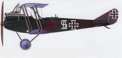
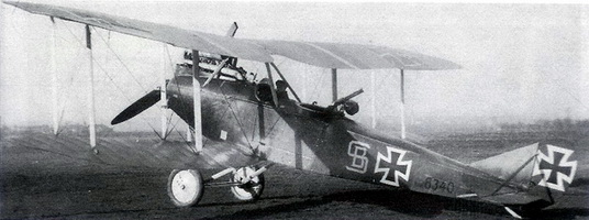
RUMPLER C.IV C.8340/17 CAMOUFLAGE RESEARCH AND SELECTION
The choice of camouflage scheme was an interesting exercise. In Windsock Datafile 35, I noted the structural problems encountered by FA 18 in March 1917 using a few early-production Rumpler C.IV aircraft in frontline situations. There was a total recall of completed Rumpler C.III and C.IV machines that had to be returned to the factory for reinforcement modification of the rear fuselage. The Frontbestand (Frontline Inventory) for the Rumpler C.IV shows that only 24 were at the front at the end of April 1917. These were possibly modified C.IVs yet to be returned. By the end of June 1917, the inventory shows 122 aircraft at the front. Taking a small step back in time, Idflieg issued a directive effective April 1917 that aircraft at the front were to be camouflaged in what I term as the "lilac" scheme, which is composed of two colors on the upper wing surfaces and fuselage sides of lilac of a light, grayish purple shade and dark olive green. Virtually every photo in Windsock Datafile 35 shows a Rumpler C.IV in a relatively standard scheme which reflects only two colors. The preceding Idflieg camouflage scheme of Summer/Fall 1916 was the three-color "red/brown, dark green, light green" version most commonly seen on Albatros aircraft of the time. This three-color scheme is not present on Rumpler C.IV aircraft. The other alternative is the even earlier Idflieg two-color scheme of "red/brown and dark green" that caused some confusion and the loss of some German aircraft because they looked like French aircraft which also displayed, back then, a similar two-color scheme of "chocolate brown and grey/green". I believe that these modified aircraft were already finished or possibly re-finished in the "lilac" scheme.
I carefully reviewed again and again the photos in Windsock Datafile 35 and Das Propellerblatt E2. I created a 3-View worksheet as I always do for aircraft I am going to build. It is part of the research process. Drawing No. 29 is a working camouflage scheme for C.8340/17. Not many of the photos show all aspects of the photographed subject. Nonetheless, I made 15 drawings using pencil to shade the camouflage that could be discerned. Some had only the fuselage shaded, some only the tail that could be seen, and some only a lower wing. Of significance in the Rumpler C.IV "lilac" scheme that appears in most of these drawings is the standard application of the upper wing, upper tail, and vertical tail surfaces. For example, note the alternating color bands of the upper wing in Drawing No. 29. From left to right, there are exactly nine bands, each of four ribs, alternating lilac and green. The only band of a different width is the center panel which is larger covering six ribs. Also, note the unique horizontal tail treatment and the split vertical tail surface. Overall, the fuselage is painted to reveal alternating colors from front to rear. The only variations I have seen are on the fuselage sides but the top usually takes on the scheme shown. Drawing No. 29 was only two of all the Rumpler C.IV drawings that I tinted using colored pencils. The undersides are pale blue. The red/brown color box on the drawing is for reference only.

CONSTRUCTION
1) Some consideration has to be given to the actual construction of the real aircraft. For this I relied on Windsock Datafile 351 and German Aircraft of the First World War 6.
2) Fuselage Prep: The fuselage comes in two halves with some internal components that have to be built up first. The kit comes with a cockpit floorboard, observer's "stool", instrument panel, rudder bar, control column, gas tank, and pilot's seat. Not much else in the way of detail was provided including the inner sides of the cockpit area. I used Windsock Datafile 35 photos to try and scratch build as much detail as possible. For cables and wires I used fuse wire, solder wire, brass rod. . . in effect, anything that would appear to look like a busy cockpit. I added the following scratch built items: seat belts, wireless transmitter, internal bomb rack, miscellaneous gauges, boxes, and more wires. I painted most of these items as I went along and painted a few after the subassembly was complete.
3) Engine: Next, I worked on the engine which has to be glued to the front cockpit bulkhead. The instructions don't tell you that the Mercedes D.IVa engine has a horizontal tilt. This was done by the aircraft's engineers to fit the engine into a compact space. I had to do a lot of trial fitting to make sure that the other components (manifold, exhaust) would fit properly. When I was satisfied, I glued the engine to the bulkhead. I painted engine details after the glue set up.
4) Fuselage Assembly: With the engine and cockpit subassemblies ready, I glued both to one fuselage half, always checking for alignment and fit. I glued the other half, got everything lined up, wrapped the nose and tail in rubber bands, checked alignment one more time, and let everything set up.
5) Tail Unit: The tail comes in three pieces with elevators attached to the horizontal tailplane and rudder attached to the vertical stabilizer. The advantage of resin is that it allows the use of super glue as an adhesive which has a quick setup time. As these were drying, I constantly checked for alignment to make sure none of the tail components slipped out of place. When completely dry, I strengthened the tail unit with small diameter brass rods instead of the flimsy resin parts that were supplied. I pre-drilled all appropriate holes, hand fitted each strut, and glued them in place.
6) Tailskid: The resin tailskid was sent off to the spare parts tray. I hammered out a piece of brass rod to get the rounded rectangular cross section. I bent the rod to get the correct curve and cut it to length with a little extra to be inserted in the location hole . I drilled out a hole on the bottom of the rear fuselage and trial fitted the tailskid. After a slight bit of drilling and trimming, I glued the tailskid in place. When it was dry, I added a touch of 5-minute epoxy to the end of the tailskid to simulate the steel "shoe" that actually touches the ground.
7) Landing Gear: I have not met many landing gear assemblies that I liked directly from the kit. Most are flimsy at best. Using the kit's landing gear and drawings as patterns, I made the landing gear struts cut from flattened brass rod. These were radically bent to make a single subassembly having two struts bent to the correct angle. The axle was then soldered to each strut subassembly. A small amount of sheet lead was folded over the axle to make the fairing. The whole landing gear and axle subassembly was fitted to the fuselage and checked for alignment. Some holes were drilled a little deeper and some struts were trimmed. Again, super glue was used to attach the landing gear to the fuselage. In this case, I used a lot of support to keep the fuselage and landing gear squared up until it was set.
8) Lower Wings: attaching the lower wings was straight forward. The fuselage molding has a projection that exactly matches the wing. The problem was lining up the brass pins I decided to use to give it strength. This took a little trial and error because I used two pins per wing and had to make sure the holes were lined up. When all was okay, I joined the wings to the fuselage with super glue. Dihedral was slight but important. I used a couple of pieces of scrap material to balance the wings while they set up.
9) Cabane Trestle: The kit expects you to use the four nearly paper-thin resin struts to build up the cabane trestle subassembly. To simplify the method I used, I cut two pieces of brass rod to slightly more than the lengths of the two front and two rear struts. After pounding the brass flat to approximate the cross-section of the struts, I bent each to an acute angle. I took a piece of brass rod and soldered it to the apex of each "V". This is the same method I use to create landing gear strut assemblies. The lengths of each strut were trial fitted and trimmed. The end of each strut was sanded down to fit deeply into the fuselage for strength. Trial fitting with the upper wing was done several times to insure proper wing gap and stagger. The completed trestle assembly was then glued to the fuselage.
10) Upper Wings (First Attempt): Here's where the problems with this kit multiplied. After reading a couple of reviews on this kit, I was so concerned about the resin wings and their tendency to droop, that I over compensated with dihedral on the lower wing and did not heed the advice of cutting the upper wing in two. I proceeded to glue the struts to the lower wing. When they were dry, I glued them and the cabane trestle to the upper wing and, voila, it didn't come out right! The center of the wings when viewed from the front looked good but the outer section of the wings drooped badly. What to do?
11) Upper Wings (Second Attempt): The incident that gave me another chance at wing assembly was the accidental dropping of the Rumpler C.IV model off the shelf and onto the floor. Good. Now I can start over. With the upper wing removed, I dipped the aircraft into a sink full of hot water, allowing the resin to soften just enough to adjust the dihedral a little more radically. When the upper wing is forced down onto the struts and pinched a bit until the super glue dries, the radical dihedral mostly disappears. Well, it was good enough for me. I checked for stagger, gap, alignment and let it dry.
12) Rigging: Reinforcing the wing and strut joints is done in the rigging step using .007 music wire. During the prep phase, all of the wing rigging holes were pre-drilled. Now, in the rigging phase, all I have to do is cut and fit each individual strut, flying, and landing wire, one at a time starting with the strut wires. This takes a long time. I will try monofilament thread on my next model. Landing gear wires were added front and rear.
13) Control Wires: This kit does not include a photo-etch sheet. Most kits have a sheet which includes control horns. For the Rumpler C.IV, I decided to make my own out of thin plastic card stock. This was tedious and the plastic control horns were not as accurate as photo-etched control horns. When the plastic pieces were made, they were super-glued in place and allowed to dry. I used .007 music wire for the rudder and elevator control wires. Aileron wires, one on each wing, were simply cut to size and fitted into pre-drilled holes. On my early models, I started off using .15 music wire which was the smallest diameter I could get at my local hobby store. It was too large so I found a website that offered music wire in different sizes. I purchased .009 and used that on a couple of models but was convinced that the size was also too large for 1:48 scale. Subsequently, I purchased .007 music wire and used it on this model but I am still not satisfied. Besides, using monofilament thread will be easier to install, but .005 which is commonly available in fabric stores in dark gray and black is a bit undersize. More on that issue when I describe my next model.
14) Observer's Gun Ring: There are a number of photos available of the observer's cockpit and all of its hardware including the machine gun mount, machine gun rest (keeps the gun secured for take-off and landing), the hand holds for turning the ring, and the Parabellum itself. Except for the Parabellum machine gun, all of the other parts were scratch-built.
15) Windscreen: These varied widely and I opted for one that approximated the aircraft I modeled. This was cut from clear plastic material used in packaging fruits and vegetables. It's thin enough to coax into shape and easy to cut.
16) Radiator Pipe: I added the water pipe from the engine front to the wing/strut-mounted radiator.
17) Propeller: I painted the propeller in acrylics, added a several dark brown stripes representing laminations, added three or four shades of colored pencil, and rubbed these down to give it a wood-grain finish.
Additional construction photos can be found here: Rumpler C.IV Construction Article
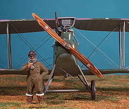
CAMOUFLAGE AND MARKINGS
Camouflage colors used on the upper surfaces and fuselage sides is almost always referred to as irregular patches of dark olive green and lilac. Under surfaces and wheel covers are described as pale light blue. Wing struts, landing gear struts, and metal components are light gray often referred to as a light grey/green. The engine manifold is wrapped in asbestos and appears white.
My preference for painting World War I aircraft is Misterkit for which I have several "back-ups" either straight from the bottle or mixed (such as Humbrol, Vallejo, Andrea, Model Master). Here is a table of colors I used on this model. Note that "mauve" or "lilac" is a light grey-purple.
PAINT COLOR SWATCHES
 |
Misterkit MKGC05 Albatros Dark Green |
 |
Misterkit MKGC02 Albatros Mauve |
 |
Misterkit MKGC03 Albatros Pale Blue |
 |
Vallejo Acrylic Mix of VC0907 (Light Pale Blue Grey), VC0885 (Pastel Green), and VC0866 (Grey Green) |
 |
Andrea ANXC18 Slate Grey (for the tires) |
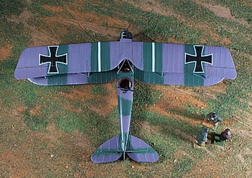
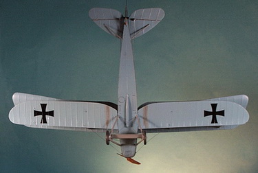
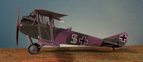
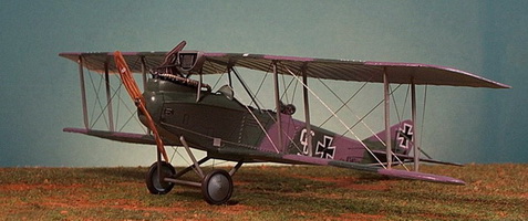
The Planet Models 1:48 scale kit of the Rumpler C.IV offers decals for two aircraft, C.6773/16 and C.8500/16. I used the Eisernkreuz insignia, the nameplate decal, the rigging packet decal, and the propeller decals. I made my own decals for the white "SB" motif, the black weight table, and the black serial numbers at the rear of the fuselage. I found a sheet of white decal paper that I cut into two strips to make the upper wing identification stripes barely visible in the photograph. After all decals had been applied, I oversprayed the entire aircraft model with Minwax "Clear Satin".
GALLERY OF PHOTOS
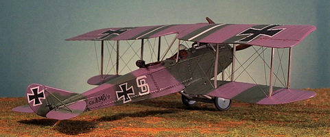
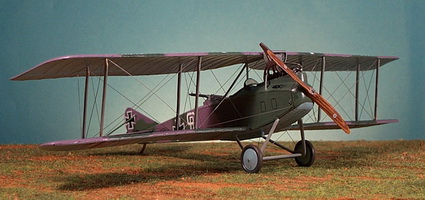

------------------------------------------------------------------------------------
SPECIAL THANKS TO WALTER WERNER OF DAS PROPELLERBLATT AND TERRY "TAZ" PHILLIPS
------------------------------------------------------------------------------------
BIBLIOGRAPHY AND END NOTES
1 Rumpler C.IV, Windsock Datafile 35, by Peter M. Gross, Albatros Publications, Ltd., Berkhamsted, Hertfordshire, UK, 1992.
2 Imperial German Army 1914-18: Organization, Structure, Orders-of-Battle, Hermann Cron, translated by C. F. Colton, MA, Helion & Company, 2002.
3 Casualties of the German Air Service 1914-1920, Norman Franks, Frank Bailey, and Rick Duiven, Grub Street, London, 1999.
4 Das Propellerblatt, Nummer E2, 2007, "Otto Semar - 'Erinnerungen aus Großer Zeit' by Walter Werner and Prof. Dr. med. Dieter Groschel, Munchen, Germany, 2007.
5German Air Forces 1914 -18, by Ian Sumner, Osprey Elite Series 135, Osprey Publishing, Ltd, Oxford, UK, 2005.
6German Aircraft of the First World War, by Peter Gray and Owen Thetford, Putnam & Company Ltd, London, 1962.
.jpg) |
| RICHTHOFEN AND MORITZ 1917 1:32 (54mm) SCALE BY ANDREA |
GO TO?