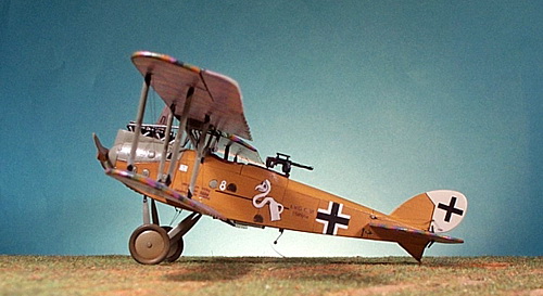
|
ISSUE NUMBER 8 |
HISTORICAL MINIATURES BY GEORGE GRASSE |
MAY 2010 |
HISTORICAL MINIATURES JOURNAL ISSUE NUMBER 8
BY GEORGE GRASSE
BUILDING THE 1:48 SCALE BLUE MAX GERMAN LVG C.VI C.1589/18 of FA(A) 286b, WESTERN FRONT 1918

PURPOSE AND KIT DESCRIPTION
The 1:48 scale WW1 airplane covered in this issue is an original, old Bluemax BX0204 1:48 scale LVG C.VI plastic injection molded kit. The Bluemax line was acquired by Freightdog some time ago and most of the Bluemax 1:48 scale kits have been re-released. I will finish the aircraft in the "Vogelkopf markerieng" of Flieger-Abteilung (Artillerie) 286b, FA(A) 286b for short. My model is based on the crash photo of LVG C.VI C.1589/18 black "8" probably flown by Sgt Jakob Hechenberger (P) and Ltn d R Karl Althammer (O) both of whom were killed in this aircraft on 1 November 1918. This information comes from Das Propellerblatt Nummer 1, Sommer 2001 and Casualties of the German Air Service 1914-1920. The circumstances of the crash are not clear so it could have been a landing/takeoff mishap or the result of combat.
The kit is quite basic and overly thick on the plastic especially the fuselage halves. In fact, the white metal fuselage formers provided for the cockpit area do not fit at all and I had to make my own out of thin plastic sheet stock which I will explain later. All of the main components are plastic supplemented by a bag of white metal parts for the aforementioned fuselage cockpit formers, landing gear, wheel axle, wheels, cabane struts, observer's gun ring, Spandau lMG08/15, Parabellum LMG14/17 with telescopic sight, exhaust stack, top wing center section, and control column. Decals could make two LVG C.VI aircraft of unknown units (I hate it when manufactures do this) and includes small decals for instrument faces, strut markings, LVG logos, and two thin black datum lines. However, except for the earliest prototype aircraft, the LVG C.VI hand all fabric surfaces finished in printed camouflage material and NONE are provided in the kit. Freightdog Models has taken over the production and release of Bluemax kits including this one. The kit I am building is an original limited edition, number 1384 out of 1500 produced. You can check out the Freightdog website for all of the 1:48 scale Bluemax kits presently available at http://www.freightdogmodels.co.uk/index.php?cPath=14_17&sort=2a&filter_id=45.
Not supplied in my kit are a number of items which I will detail in the step-by-step Construction section below. I used the following after-market accessories:
MAJOR CONSTRUCTION COMPONENTS OF THE LVG C.VI
Construction of the fuselage was of wood formers covered with thin plywood. Only the front of the fuselage was covered with metal panels to enclose the engine. A number of smaller circular access panels and slotted louvres were scattered over the front. The large Benz Bz.IV engine was open at the top surrounded by high metal panels. Overall, the fuselage was shorter than the C.V and a spinner was not incorporated.
The tail unit was quite similar to the earlier C.V except the surface area was increased for more responsive handling. The plywood covered vertical fin is counterbalance by the under-fin that reinforced the tailskid, another C.V similarity. The horizontal stabilizers, balanced elevators, and rudder were of wood stringers covered in printed camouflage fabric usually in the 5-color pattern. The landing gear struts were tubular steel faired over in wood. The axle was buried in an aerofoil section and the wheels were sprung with bungee cord.
The wings were substantially changed in the C.VI in both shape and construction. Wood members were used throughout, Gray & Thetford suggesting that this was a sure sign of material conservation. The upper wing was staggered forward 10 inches to increase lift so as to offset the dramatic decrease overall in wing area from 42.7 square meters in the C.V down to 24.6 square meters in the C.VI. Additionally, the unbalanced ailerons were streamlined into the wings. All of this made the C.VI much more nimble. Wing surfaces were covered in mostly 5-color printed camouflage fabric. Cabane struts were of the "N" style reinforced by two sets of cross braced rigging wires on the front deck. The eight wing struts were heavily reinforced with steel "shoes" and fully rigged.1
LVG C.VI PRODUCTION
The initial research into the production orders and serial numbers appeared in LVG C.VI Windsock Datafile 17 by Peter M. Grosz in 1989, revised second edition in 1999, and a subsequent updated release LVG C.VI at War by Ray Rimmel 2009. Table 1 below shows the order status taken from these publications and presented here.
Table 1: Summary of LVG C.VI Aircraft Orders and Serial Numbers
|
Month Ordered |
Qty Ordered |
Serial Numbers |
Notes |
|
Oct 1917 |
3 |
14400 -14402/17 |
Prototypes |
|
Mar 1918 |
250 |
1497 - 1796/18 |
Includes LVG C.V |
|
May 1918 |
100 |
3900 - 3999 |
all LVG C.VI |
|
June 1918 |
150 |
4750 - 4899/18 |
" |
|
Jul 1918 |
100 |
7150 - 7249/18 |
" |
|
Jul 1918 |
200 |
7600 - 7799/18 |
" |
|
Jul 1918 |
50 |
08.101 - 18.150 |
Austria-Hungary but cancelled |
|
Aug 1918 |
200 |
8900 - 9099/18 |
all LVG C.VI |
|
Oct 1918 |
200 |
11100 - 12099/18 |
serials not verified; nor built ? |
|
Totals |
1253 |
n/a |
n/a |
When the prototypes were approved in October 1917, current C-Types at the front were showing signs of age relative to the improvements in aeronautical engineering and engine development. The LVG C.VI was designed to replace these aircraft in the FA(A) units directly supporting frontline infantry divisions. The aircraft had to be more powerful, lighter in weight, fitted for photographic equipment for short-range reconnaissance, carry a wireless sending unit for artillery spotting, have usual front fixed and rear flexible machine guns, and be capable of carrying a light armament load for local ground attack support including small bombs and grenades. Powered by the same Benz Bz.IV 200 hp engine as the LVG C.V, the C.VI was not a significant improvement, perhaps marginally better, but with some production efficiencies in material and method. However, production problems delayed the deployment of the first batch of 250 aircraft which possibly reached front line units in early May 1918. The first LVG C.VI aircraft show up in the frontline inventory as of the two-month period ending in June 1918. The Frontbestand for the C.V and C.VI is shown below in Table 2.2
Table 2: Frontbestand for the LVG C.V and C.VI 1917-18
|
|
1917 |
1918 |
|||||||||
|
Feb |
Apr |
Jun |
Aug |
Oct |
Dec |
Feb |
Apr |
Jun |
Aug |
Oct |
|
|
C.V |
- |
- |
- |
98 |
219 |
446 |
504 |
565 |
312 |
133 |
? |
|
C.VI |
- |
- |
- |
- |
- |
- |
- |
- |
173 |
400 |
? |
|
Subtotal |
- |
- |
- |
98 |
219 |
446 |
504 |
565 |
485 |
533 |
? |
|
Total C-types |
934 |
1029 |
1184 |
1302 |
1487 |
1508 |
1475 |
1611 |
1966 |
2061 |
1821 |
|
LVG % |
- |
- |
- |
7.53 |
14.73 |
29.58 |
34.17 |
35.07 |
24.67 |
25.86 |
? |
DEPLOYMENT OF THE LVG C.VI
The German method of providing aircraft to FA and FA(A) units was to issue a replacement aircraft from the AFP (Armee Flugpark) in the Armee area in which the unit operated. Many of the FA and FA(A) units operated in direct support of a specific front line infantry division on a specific part of the front line. Because the older Schutzstaffeln were all pulled from directly escorting these units, renamed Schlachtstaffeln, and used exclusively in the ground attack role, the front line FA and FA(A) units now had to provide that duty, i.e., escorting/protecting their own aircraft. To this end, it was decided by decree that all FA and FA(A) unit designated as front line infantry division support units would have their aircraft establishment increased from six (6) to nine (9) aircraft.
This verstärkt (or increase) to the Sollbestand (or unit aircraft inventory) allowed for the addition, in general, besides six two-seaters such as the LVG C.VI, DFW C.V, Rumpler C.IV, for division work, to be augmented by two escort aircraft, usually the Hannover CL.III/IIIa, and one infantry contact aircraft usually one of the armored AEG, Albatros, or Junkers J-Types. Now, the LVG C.VI would usually have one Hannover as an escort, sometimes none, sometimes two, depending on the mission. The LVG C.VI was certainly not protected enough to perform low-flying infantry contact patrols. This type of mission required an aircraft with armored protection for the crew and engine and be capable of some form of ground attack but, more importantly, be able to flow "low and slow" to determine friendly troops positions, located threatening enemy activity, and communicate their findings back to division and corps headquarters. A combination of all these types of missions were flown by units several times a day especially when the Allies launched their offensives near the end of the Summer of 1918.
So, when a unit such as Flieger-Abteilung (Artillerie) 286b, lost a two-seater division aircraft, AFP A (A = Armee Abteilung A) pulled out a new LVG C.VI, perhaps even a new crew if needed, and sent it forward to the unit's Flugplatz (aerodrome).
WESTERN FRONT 1918 HISTORICAL BACKGROUND
By the time the LVG C.VI deployed to front line units, in May-June 1918, the great Ludendorff offensives of March and April was concluded with disappointing results. By this time, American troops were entering the front lines and American air units were in the air. Back in 1917, OHL had predicted that unless the Allied front was broken and Britain and/or France were knocked out of the war, Germany would be hard-pressed to contain a re-invigorated Allied army with literally hundreds of thousands of fresh American troops that would allow for offensive operations on must sectors of the Western Front. Weight of numbers in terms of infantry, machine guns, artillery, and aircraft would soon come to bear on all sectors such that a break-through would eventually cause the German Army to collapse.
Not much in the way of aviation technology was available to the Luftstreitkräfte in the Summer of 1917. The Fokker D.VII, the LVG C.VI, the Rumpler high-altitude photo aircraft, and the giant bombers could not be produced in sufficient quantities but worse, the mathematics of crew training and availability was on a permanent descending curve. As more Allied aircraft filled the skies, there were fewer available German aircrews to man aircraft. Always outnumbered against a pressing, offensive-minded enemy, more and more of the stable of great German crews were being lost to uneven combat encounters including fighters and anti-aircraft fire. Fewer two-seaters of the FA and FA(A) units were able to penetrate Allied air space and obtain photos and visual sighting data. Low-flying Schlachtstaffeln (ground attack) aircraft were especially subject to ground fire and patrolling Allied fighters.
All of the German innovations in military aviation were being matched by the Allies, at least enough to marginally reduce their effectiveness. True, the Fokker D.VII was an exceptional fighter even against two- or three-to-one odds, but four- or five-to-one odds could not be sustained. Imagine this scene into which the two-seaters had to operate flying their steady, predictable flight patterns to direct artillery fire or obtain photos or visually spot Allied movements. More and more of these missions had to be protected not only by higher-flying fighters, but at least one and sometimes two additional escorting two-seaters were necessary to protect the really important aircraft. This was the job of the LVG C.VI: get battlefield intelligence.
FLIEGER-ABTEILUNG (ARTILLERIE) FA(A) 286b
Flieger-Abteilung (FA units) were originally created to perform specific long-range, deep-penetration, high-altitude reconnaissance missions both visually and photographically. As such, they were assigned to Armee and Korps levels. Flieger-Abteilung (Artillerie) (FA(A) units) were created to work specifically with front line infantry divisions to co-ordinate artillery fire, locate enemy targets, and perform short-range reconnaissance.
Flieger-Abteilung (Artillerie) 286b was created on 8 December 1916 by renaming Feldflieger-Abteilung (Artillerie) 101b. The small letter "b" identifies this as a Bavarian unit. All FA and FA(A) units were created near the end of 1916 and into 1917 as a result of a major reorganization of the Fliegertruppe into the Luftstreitkräfte to become an independent air force. A complete record of this transformation is available on line at http://www.frontflieger.de/2alb.html or in various issues of Das Propellerblatt.3
FA(A) 286b was a "verstärkt" unit and had its establishment increased to nine aircraft per War Department (Kriegs Ministirium) order KM Nr.928/17 dated 7 January 1918. In general, such a unit had a mix of six (6) two-seater army cooperation aircraft, two (2) escort aircraft, and one (1) infanterieflugzeug (armored infantry contact patrol aircraft). Throughout this last year of the war, the actual mix varied greatly on any given day due to losses and availability of replacement aircraft. When a front line infantry division was withdrawn for rest, the FA or FA(A) unit for that sector had to re-establish cooperation procedures with the new infantry division. Often, experienced FA and FA(A) units were themselves withdrawn usually to support a neighboring sector's offensive or defensive operations. It is quite difficult to trace the orders of battle for Luftstreitkräfte FA and FA(A) air units including Jastas and Schlastas, especially during the relatively mobile battles of late Summer and Fall 1918 when units were shifted from one Armee to another.
From the online German Frontflieger website (address cited above), I found one order of battle for 1.Armee for the Kaiserschlacht offensive in March 1918. FA(A) 286b was assigned to Grufl 104, the aviation element for Gruppe Brimont, a corps-level unit of 1.Armee5.
According to French Intelligence analysis of the location of German FA, FA(A), and Schlasta units in the last three months of the war, FA(A) 286b operated under Army Abteilung A in September and October 1918 but apparently was reassigned to 1.Armee in November 1918 probably as a reinforcement to the now-crumbling Reims sector. The Armee A Abteilung sector was relatively quiet throughout the war, mostly in the Vosges mountain country. It's neighbor to the south, Army Abteilung B continued the Western Front from the Vosges to the Swiss border. Air activity was another matter. French bomber units and Britain's Independent Air Force were quite active over the lines, stabbing at German industrial centers just beyond the Rhine. Photographic missions were frequently made in order to spot Allied bomber concentrations on the ground especially in the area running from Nancy in the north to Epinal in the south. Such reconnaissance missions by German air units including FA(A) 286b were fraught with danger from improved anti-aircraft defenses and French SPAD fighters.
During this period, the last months of the war, FA(A) 286b seems to have had the following aircraft in its inventory but I don't known their numbers or serials: AEG/Albatros/Junkers J-Type, DFW C.V, Halberstadt C.V, Hannover CL.III or IIIa, LVG C.V, LVG C.VI, and Rumpler C.IV.
LVG C.VI C.1589/18 RESEARCH
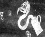
My 1:48 scale model is based on one photograph that appears on the cover of Das Propellerblatt Nr. 1. This photo and others plus artistic aircraft profiles are used by the author, Reinhard Kastner, to tell the story of the unusual "Vogelkopf" unit marking of FA(A) 286b as shown below along with the crash photo of C.1589/18. Unfortunately, information about the crew and circumstances are not positively known from my research. I judged from the leaf-less trees in the background, that the photo was taken in mid to late Fall 1918. Also, the severe damage to the aircraft must have killed or seriously wounded one or both of the crew. Two FA(A) 286b crews were involved in fatal crashes at this time: one on 31 October 1918 at St. Ferquex (Vzfw Heinrich Hofmann, pilot) and another on 1 November 1918 at Écly-Gomont (Sgt. Jakob Hechenberger, pilot, and Ltn d R Karl Althammer, observer, both killed.6
| LVG C.VI C.1589/18 crash photo. This photo does not reveal the printed camouflage pattern but other sources have concluded that the 5-color pattern was the predominant one used. Note the "Vogelkopf" unit insignia and small white numeral "8" towards the front of the aircraft. (Das Propellerblatt, Nr. 1, cover photo, Reinhard Zankl, editor). | LVG C.VI C.1589/18 crash photo inverted enlargement. The author has found three other FA(A) 286b aircraft marked. | LVG C.VI C.1589/18 profile. This nicely done profile clearly identifies all of the markings needed to reproduce this aircraft in 1:48 scale. I was absolutely intrigued by the "Vogelkopf" as it represents one of the few army cooperation units that used consistent unit markings late in the war. (Das Propellerblatt, Nr. 1, profile by Reinhard Zankl). |
|
|
 |
 |
In order to eliminate one or the other (hopefully not both!), I went to Google Maps to try and find the two sites and then match them to sites in French claims using The French Air Service War Chronology 1914-1918.7 The crash photograph of C.1589/18 appears catastrophic resulting from a steep dive right into the ground. If true, both occupants were probably killed. This is why I've zeroed in on the 1 November 1918 crash of Hechenberger and Althammer. The French claims for that day list five "2-seaters" at these locations: N. Novy, Sissone, Croix-aux-Mines, Semuy, and Quatre-Champs. When I entered Écly, I reviewed the immediate area and found Gomont. This means that the German entry of Écly-Gomont represents a line between to two towns of about 12 kilometers and was meant to be a generalization of the crash site for the records. So, the question is, "What would a French aviator record as the site for his aerial victory"? Again, I am assuming that C.1589/18 was shot down in the 1.Armee sector.
The principal city in the immediate area is Rethel the central command point for von Below's 1.Armee. So, it seems that FA(A) 286b was, in fact, transferred to 1.Armee to reinforce that sector against Allied offensive pressure. I noted the following sites based on distance from Rethel: Écly- 10 km NW, Novy-Chevieres 5 km NE, Sissone 30 km WNW, Semuy 25 km E, and Quatre-Champs, and Quatre-Champs 35 km ESE; but one site, Croix-aux-Mines, was found in the Vosges sector about 40 km East of Epinal. This one bit of information could possibly put the crash-site in the Vosges sector while FA(A) 286b was still attached to Armee Abteilung B; however, this is suspect because both FA(A) 286b AND Spa.103 would have had to move to that sector. I believe that one or more of the elements of this claim is/are in error.
Of the all the entries for 1 November 1918, five claimed "2 seater", seven claimed "EA" (for enemy aircraft), three claimed "scout" (presumably single-seat fighters), one claimed a balloon, one claimed a "Fokker" (presumably a Fokker D.VII, and one claimed a Halberstadt C (probably a CL.II or CL.IV). Table 3 summarizes my findings for French "2-seater" claims on 1 November 1918 in the 1.Armee sector which is where, in my opinion, FA(A) 286b was based at the time. It is possible that it was, in a matter of days, moved to the 1.Armee sector as reinforcement when 1.Armee was in danger of being overrun by French and American troops.
Table 3: Summary of 1 November 1918 French Victory Claims One of Which is Possibly LVG C.VI C.1589/18
|
French Pilot(s) |
Escadrille |
Site |
Time |
German Sector |
|
Sgt. Lalanne & Sgt. Gautre |
Spa.31 |
North of Novy |
12:15 |
1.Armee |
|
Lt. Casale & Adj. Fabre |
Spa.38 |
Sissone |
12:35 |
1.Armee |
|
Lt. René Fonck |
Spa.103 |
Semuy |
14:35 | 1.Armee |
|
Captain d'Argueeff |
État-major GC 21 |
Quatre-Champs |
13:00 | 1.Armee |
MODEL CONSTRUCTION
I have relied on a number of references for details: 1) Windsock Datafile 17 LVG C.VI (WDF017 for short, the revised 1999 edition) by Peter M. Grosz; 2) Windsock Datafile 138 LVG C.VI at War (WDF138 for short) by Ray Rimmel; 3) Das Propellerblatt Nr. 1 "Markierungen (1): die bayer. Fliegerabteilung (A)286 im Jahre 1918" by Reinhard Kastner; 4) Wingnut Wings LVG C.VI 1:32 scale kit instruction booklet, especially step-by-step color assembly drawings of the interior, multi-view color profiles, and the detail on the decal sheets. My own step-by-step construction narrative below includes a few photos but a more complete history of building this model with construction "in-progress" photos is maintained on my "World War 1 Aircraft in 1:48 Scale" website section; click here for more photos of the LVG C.VI construction process.
1) A Discouraging First Step with the Fuselage: I first started to work on this kit back in October 2009. Within minutes, I discovered that the three white metal formers to be glued in place on one fuselage side, were too large and prevented the fuselage halves from being joined. I was discouraged so I boxed up the kit and put it away into storage. "This kit can't be built!", I wrote in my notes. In late December 2009, after reviewing the Wingnut Wings 1:32 scale LVG C.VI instruction booklet, it dawned on me that I could make my own formers from thin plastic sheet.
2) Fuselage Formers: the first former built was the engine firewall. To fit between the fuselage halves, the scratch-built former was less wide. This suggests that the kit formers were made after the fact since they match the WDF drawings but won't fit because of the overly thick fuselage casting. Using the WDF drawings and the Wingnut Wings instruction booklet, I was able to configure the instrument panel former, pilot's cockpit rear former, and two observer's cockpit formers, front and rear. These were all glued to one fuselage half and allowed to dry overnight with the other fuselage half just pressed on for fit.
3) Floorboard: the formers had to take into account a floorboard not supplied in the kit. The main gas tank had to be scratch built onto which the pilot's seat from a Copper State AEG kit was glued. After trial fitting several times, the floorboard was fitted and glued to the one side that already had formers attached.
4) Instrument Panel: I cut a piece of plastic stock to the correct shape for the instrument panel and added Eduard pre-painted and Copper State gauges and scratch-built switches based on WDF photos and the Wingnut Wings instruction booklet. The panel was glued to the pilot's forward former.
5) Fuselage Cockpit Details: I added a number of scratch-built items such as boxes, wires, gauges, observer's "writing" desk, observer's bench seat, map case, rudder bar, control stick, camera, seat belts, and a neat little copy of the Wingnut Wings wireless transmitter and trailing wireless antenna spool. Some of the fuselage internal structural members were painted in grey-green and some, which are wood, were painted tan/orange. Most internal components were painted a metallic black.
6) Engine Compartment Prep: I assembled the Benz Bz. IV engine and test fitted it to the fuselage halves. A little cutting here and there was necessary for the correct fit. The engine was painted a metallic semi-gloss black with matte aluminum induction pipes. The engine compartment was painted light grey-green. When the two fuselage halves were test fitted together, only the top half of the engine could be seen.
7) Lower Wings: Before joining the fuselage halves, I wanted to address the lower wings. My habit is to insert two brass pins on each lower wing to carry the load when the wings are joined to the fuselage. However, I have to be careful that the pins do not "run" into the cockpit section and cause damage. After careful measuring, I located where I wanted the pins and marked both the fuselage and wings. I drilled out the corresponding holes for the short brass pins, inserted them into the wings, and test fitted the wings to the fuselage. The wings were then set aside, over-sprayed with clear semi-gloss polyurethane so as to be ready for the tedious 5-color decal application later on.
8) Upper Wings: I decided to join the two upper wing outer panels to the small center section panel using brass pins and super glue. I oversprayed the upper and under surfaces with semi-gloss polyurethane to get them ready for decal application. Now, the wings are ready for that step later on.
| 9) Fuselage Assembly: I reviewed the work I had done in the engine compartment, on the engine, the pilot's cockpit, and the observer's cockpit to be sure that details were added. Now is the time to do these sorts of things. When I was satisfied with the details added to the interior and the trial fit of the fuselage halves, I went ahead and glued them together, holding them in place with a couple of ordinary rubber bands. Note the protruding brass pins for the lower wings. I allowed 24 hours for the plastic cement to completely set. After that, I applied Monograms "Red Putty" to seams, let it dry, and sanded seams down, and over-brushed the surfaces with my mix of "liquid plastic". One more light sanding with 400 grit cloth for smoothness. The kit's tailskid was replaced with a shaped brass rod. |
|
10) Painting the Wood Fuselage Finish: This step got off to a rough start. In the past, I have painted Andrea ANAC15 Ochre as the base coat over which I used colored pencils to replicate the wood fuselage grain (see Albatros C.X, HM Journal Issue 5). When the Ochre base was dry, I noted that there were discrepancies on the model's fuselage panel lines relative to WDF017, WDT138, and Wingnut Wings. When I tried to scribe the lines through the Ochre paint, I experienced chipping of the paint. In the end, the base coat of Ochre was uneven and just looked bad. I sanded down the rough spots and tried to correct the finish by over-painting with Model Master ME1735 Wood which made it worse! Then, I understood what was happening. I should have prepared the surface of the plastic with a thin sprayed-on layer of white or gray model primer after taking care of panel lines. In short, I corrected by removing the paint using a small piece of cloth and lacquer thinner which came out quite well (see the WOOD FINISHED FUSELAGE section below for more details). At any rate, I mixed a batch of Winsor & Newton oils on a palette and applied this to the fuselage. In the end, the finish came out nicely after it was "baked".
%20LVG%20C.VI%2002.jpg)
11) Fuselage Details: Painted the rudder white; painted all metal panels and louvres my mix of light gray-green; painted the pilot's cockpit coaming Andrea ANXC50 Leather Brown; installed and painted the observer's gun ring; primed the Spandau machine gun, gave it some detail including forward ring sight, cartridge chutes, and a coat of gunmetal black then installed it. I used a thin mixture of my dark brown/black liner to highlight panel lines, louvres, and access panels. Detailed the Parabellum machine gun and painted it dark metallic gunmetal. Painted the propeller with a base coat of light ochre followed by a dark brown to simulate laminations. Then rubbed a variety of shades of colored pencils to achieve a wood grain finish.
12) Landing Gear: constructed each "V" landing gear strut from one piece of Strutz bent to the correct shape WDF017/138 drawings as a guide. Cut the tips off but left enough to serve as pins, bent to shape. Cut a piece of round brass rod longer than needed and wrapped small piece of lead foil to create the axle aerofoil and super glued this together. When dry, I glued the struts to the fuselage and then the axel with aerofoil to the inside apex of the "V" landing gear struts. When the landing gear was completely dry, I wrapped .10 solder around the ends of the axels to simulate the bungee cord shock absorbers. I painted the wheel covers a light grey green with medium gray tires. Then I test-fitted the each wheel to the axle ends and cut off the excess brass rod to make them fit. I did not glue the wheels yet. Next I drill a couple of holes near the rear strut fuselage contact point, inserted a PE turnbuckle, and rigged the landing gear.
13) Microsculpt 5-Color Under Surface Printed Camouflage Fabric Decals: I did decal application at this stage mostly to get the underside of the tail unit finished so it could be glued to the fuselage when the upper surface was covered. Covering is done in chord-wise strips on the wings but span-wise on the tail. I didn't have any problems applying the decals which are nicely done. The horizontal tail surfaces are in four pieces: left and right stabilizer and left and right elevators. I used the actual pieces as a template, laid out on the backside of the decal sheet and drew a pencil outline just slightly oversize: one elevator and one stabilizer. I flipped these over and cut out pieces for the other side. Each piece was dipped in water and placed on their corresponding part. Reminder: note that you have to take into account left and right as mirror images of each other. In other words, you can't make one elevator piece: you have to make a left and a right. Same with the stabilizer. Once dry after about an hour, I sanded off any excess decal. I then over-sprayed the wings and tail unit pieces with polyurethane satin. All of the wing rigging and strut holes were easily cleaned out but then I realized that the lower wing's holes, which go all the way through, would have to be patched after the rigging was super glued but the decals had already been applied. This was a mistake. The lower wing's under surface should have been left bare until all patching was completed. Now I'll have to match the decal's colors to cover up the patches.
14) More Fuselage Work: I painted the rudder white. Let it dry and over-sprayed the fuselage with polyurethane satin. I then applied lift arrow decals near the tail, the rudder's Balkenkreuz, LVG logo to bottom of rudder, rigging diagram decal, and fuselage Balkenkreuz. Additional components added were the engine sump and vent panels, engine oil tank access panel, drag wire turnbuckles on the nose, and under side nose panel fasteners. One more light over-spray to seal the decals.
15) Microsculpt 5-Color Upper Surface Printed Camouflage Fabric Decals: The upper surface decals were applied in exactly the same manner as described for the under surface in step 13 above except that the ailerons were stilled detached and the pattern applied was span-wise.
16) Rib Taping: I decided to use Techmod's 1:48 scale rib and border tape decals: light blue for the upper surface and pink for the under surface. I wanted to do the border taping in Microsculpt' s 5-color upper surface decals but I abandoned this idea and decided to paint them. More about that in the PRINTED CAMOUFLAGE FABRIC FINISH below. Here's a photo showing the finished camouflage upper surface.
%20LVG%20C.VI%2004.jpg)
17) Tail Unit: With the camouflage fabric decals on the tail unit, I was now able to glue it to the fuselage. Drilled out holes and inserted elevator and rudder control horns. These will have wires attached later.
18) Cabane "N" Struts: The kit's white metal cabane "N" struts aren't strong enough for me so I made my own out of brass Strutz material. Each "N" is made from three pieces soldered together. I left the ends which make contact with the fuselage and upper wing a little longer. I drilled out these openings and trial-fitted each "N" strut. A combination of drilling a little deeper and nipping off a little brass got me to the correct gap between wings. Here are two close-up views of progress so far. Note the border taping, landing gear, propeller, "N" struts, and engine access panels under the nose. The piece protruding above the rear of the engine is the pre-fitted radiator pipe that will be connected to the upper wing radiator.
%20LVG%20C.VI%2008a.jpg)
%20LVG%20C.VI%2008b.jpg)
19) Fuselage Decals: I made decals for this aircraft using an inkjet printer and clear decal paper. The problem with this method is the sealing of the ink with a special sealer, usually two coats, minimum. I had to make a number of unique markings: serial number x 2, work number x 4, weight table x 1, "8" numeral x 2 (in two sizes because I wasn't really sure of the fit - and in blue because you can't print white!), Vogelkopf unit insignia x 2, and my signature decal. Here's what the layout looks like. After application, I oversprayed the fuselage with matte polyurethane then painted the numeral "8" and Vogelkopf insignias in white.
|
L.V.G. C. VI 1589/18 L.V.G. C. VI 1589/18 L.V.G. C. VI 1589/18 Eras Light ITC size 6 LVG C.VI G. Grasse No.6413 Leergewicht 950kg 4039 4039 4039 4039 Nutzlast 430kg Gesamtgewicht 1380kg size 4
8 8
size 14
8 8
size 16
|
|
20) Upper Wing Preparation: the under surface of the top wing has already been covered in printed camouflage decals (see step 13). The wing fuel tank was glued in place to which was added fuel lines cut to length that will be inserted into the fuselage in the wing assembly step, below. Using .005 gray metallic monofilament thread, I glued one end of each of the 28 rigging wires to pre-drilled holes on the underside of the top wing. To complete the forward deck under the upper wing, I rigged the two pairs of cabane wires, and added a mirror to the right rear "N" strut.
21) Upper Wing Assembly: before gluing the upper wing to the brass "N" struts, I test-fitted it and checked for alignment. I had to make a minor adjustment to one of the "N" strut holes on the underside of the upper wing that allowed for some movement in order to keep the two wings aligned properly. I glued the top wing onto the "N" struts being sure that none of the rigging wires were "trapped" in super glue.
22) Interplane Rigging: there are so many dangling .005 monofilament "wires" glued to the underside of the upper wing that one has to be organized to get them all into place. It is quite possible to grab the wrong "wire", glue it through the bottom wing, and then discover your mistake after it has been trimmed. This means you have to pull out the "wire", re-drill the holes top and bottom, and run a new "wire". It's best to be organized and that is why I always start from the inside "N" struts to the outside wing tip struts. I rigged four "wires" a time letting the glue set up under the weight of metal clips dangling from the ends of the wires. For each wire, I pass it through its proper hole in the bottom wing, apply a dot of glue from the underside, and attach a metal clip for weight. When thoroughly dry, I cut off the excess, and move to the other side of the wing and glue a corresponding set of "wires".
23) Aileron Rigging: This model did not have aileron control horns so it was easy to rig a pair of wires for each aileron. I checked drawings and photos which show two wires on the underside of the top wing. Both terminate in one spot. These passed through a small hole in the lower wing and were glued there from the underside. Weights were attached until the super glue set, then the excess wire was cut off.
24) Final Details: all of the rigging holes through the lower wing were sanded smooth. This is where the application of the printed camouflage decals in step13 was disrupted by having to sand the rigging holes to a smooth finish. Some spots were worse than others so it was a matter of using new decal strips to cover up the mess or touching up with paint. Glued the radiator pipes, exhaust stack, Parabellum gun mount, and Parabellum butt travel lock.
This aircraft has a wood fuselage and I decided to finish it using artist's oils. In Windsock Datafile 138, LVG C.VI at War, page 25, is reproduced an English translation of a German memo that suggests that wood fuselages be stained a darker color using "lazur" before the fuselage is lacquered. The effect was to create a darker finish that blended somewhat with the printed camouflage fabric. The practice of clear shellacking a wood fuselage always resulted in a yellow-brown or ochre color. This "memo" was produced on 20 September 1918. It's wording suggests that stained wooden fuselage finishes were uncommon if non-existent! As we all know, shades of yellow tended to photographic much darker using the film of the period. It is easy to assume that earlier wood fuselage might have been stained darker. But who really knows?
My LVG C.VI C.1589/18 was from the first production batch ordered in March 1918 and, in my opinion, did not have a stained fuselage. Therefore, it has a natural clear shellacked finish giving it an overall yellow/light brown shade. I pre-painted the fuselage and its attached vertical fin with one coat of Andrea ANAC15 Ochre but the finish was rough and unsatisfactory. I made the mistake of over-painting that with Model Master ME1735 Wood. It was worse. So, I had to remove the paint. I did this with a small piece of cloth dipped in lacquer thinner. I carefully stroked the cloth over the paint taking off a little at a time and spreading it thinner where it did not come off. I must have done this hundred times and finally got nearly all of it off. What remained looked like the wood fuselage of a World War I airplane that has been in the basement of a museum awaiting restoration.
Over this "old" looking finish, I applied my mix of Winsor & Newton artists' oils consisting of Raw Umber, Cadmium Yellow, Vandyke Brown, and Titanium White. I just kept adding one or another of these colors plus gum turpentine to get the shade and consistency I wanted. Using a large, fine bristled brush, I painted the color onto the fuselage in one direction, horizontally, at first. When the surface was nicely saturated with paint, I wiped most of the paint from the brush and continued stroking. I did this repeatedly to remove as much paint as possible but still enough to leave fine streaks of brush strokes that simulated the grain. In a couple of places bordered by panel lines, I changed direction of the brush strokes vertically. I use a fair amount of oils on horse in military miniature painting and I always "bake" them in my oven at the lowest setting of 170o F. That works well for white metal figures but it will melt plastic! So, I use the warming draw set on low at "proofing" temperature, which is 130o F. It "baked" overnight and was absolutely dry to the touch the next morning.
PRINTED CAMOUFLAGE FABRIC DECALS
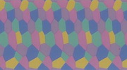
All flying surfaces are covered in 5-color printed camouflage fabric decals made by Microsculpt, in my opinion, the best on the market. My research of photos shows that many of the LVG C.VI aircraft had light-colored ribs but camouflaged taped borders around the the edges of the flying surfaces. I'm sure others would interpret this differently. Further, as to light colored ribs, it is impossible to tell if they were "salmon pink", light blue, or clear doped linen (CDL) strips. My interpretation of the original intent of the colored rib tapes was "salmon pink" for the undersurfaces and "sky blue" for the upper surfaces. CDL was probably used near the end of the war when stocks of colored tape were used up. However, it boggles my mind that camouflage strips from the same printed camouflage fabric weren't used for ribs universally. To me, it seems that the colored tapes compromised the camouflage scheme. No where have I found a German document that specifically details the application of rib and border taping.
I used Techmod's 1:48 scale rib and border tape sheet of sky blue and pink for the ribs only. I applied the sky blue tapes to all upper flying surface ribs and pink to all under flying surface ribs. This is a task I do not enjoy. Even worse, is the application of tape decals to all flying surface borders. In fact, I gave up trying to cut and apply thin pieces along the edges; absolutely not worth the effort. I decided, instead, to paint the borders. Since I was dealing with the darker upper surface scheme for border taping and I decided to do it in 4-color, I duplicated the Microsculpt decal colors as shown by mixing a combination of Vallejo and/or Andrea acrylic paints as shown in Table 4.
Table 4: Duplicating a 4-Color Upper Surface Scheme for Border Taping
| Light Green |
Vallejo VC0881 Yellow Green and Andrea ANAC24 Light Green |
| Ochre Brown |
Vallejo VC0856 Ochre Brown |
| Dark Blue |
Vallejo VC0900 French Mirage Blue |
| Mauve |
Andrea ANAC14 Purple, ANAC14 Purple, ANAC06 White |
One problem that should have been anticipated was to hold off on the lower wing under surface printed camouflage decal. To secure the strut wires, I drill through the lower wing. When the top wing is secured, I pass the rigging wires through their corresponding lower wing holes, apply a small amount of super glue, clasp the rigging wire with a weighted clip, and let it dangle until firmly dried. I then cut off the excess. When all rigging wires are in place, I will patch the holes, sand them flat, and paint over them. That works well for an under surface that is finished in one overall color. But now I have to contend with a printed camouflage under surface full of holes! I proceeded to attach all of the rigging wires, filled the holes, and had to mix up colors to match the lighter 5-color under surface printed camouflage decals. All of these colors were mixed on my palette and, as I recall, more use of pearl gray was necessary to mute the colors.
Table 5: Duplicating the 5-Color Under Surface Scheme for Touch-up Painting
| Pale Rose Brown |
Vallejo VC0803 Brown Rose, VC0944 Old Rose, and Andrea ANAC60 Pearl Gray |
| Pale Yellow Ochre |
Vallejo VC0806 German Yellow, Andrea ANXC21 Medium Gray, and Andrea ANAC51 Golden Ochre |
| Pale Light Green |
Vallejo VC0971 Green Grey and Andrea ANAC24 Light Green |
| Violet Blue |
Vallejo VC0900 French Mirage Blue, VC0811 Blue Violet, Andrea ANAC60 Pearl Gray |
| Mauve |
Andrea ANAC14 Purple, ANAC14 Purple, ANAC60 Pearl Gray |
%20LVG%20C.VI%2006.jpg)
Metal panels, louvres, and struts were painted in my mix of German Gray-Green. The remaining colors used are shown below in Table 6.
Table 6: Paint Color Swatches Used on my LVG C.VI C.1589/18
 |
Microsculpt 5-Color Printed Camouflage Fabric upper surfaces decal |
 |
Microsculpt 5-Color Printed Camouflage Fabric under surfaces decal |
 |
Vallejo Acrylic Mix for "German Gray-Green" consists of VC0907 (Light Pale Blue Grey), VC0885 (Pastel Green), and VC0866 (Grey Green) |
 |
Andrea ANXC18 Slate Grey (for the tires) |
 |
Model Master ME1730 Wood (interior cockpit wood components and base coat for artist's oil wood fuselage) |
 |
Andrea ANXC50 Leather Brown (cockpit coaming base) |
 |
Andrea ANXC49 Dark Leather Brown (cockpit coaming wash) |
 |
Model Master MA4622 White Primer (for the kit's metal parts) |
LVG C.VI C.1589/18 MARKINGS
This aircraft was marked with the usual Balkenkreuz (BK) in the traditional eight positions. I used the kit's BK markings for the wings, fuselage, and rudder. The photos and a profile published in Das Propellerblatt Nummer 1 provided all the information I needed to create my own decals for the serial number, Vogelkopf unit marking, individual aircraft number black "8", rudder work number, and weight table. I cut a thin strip from my generic black decal sheet and applied it as the datum line to the left side of the fuselage. On the underside of the fuselage, I added a small decal identifying my work, "LVG C.VI G. Grasse No. 6413".
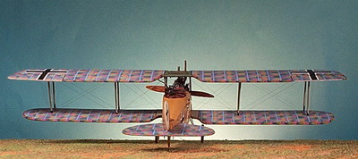
LVG C.VI C.1589/18 FINISHED PHOTO GALLERY
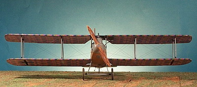
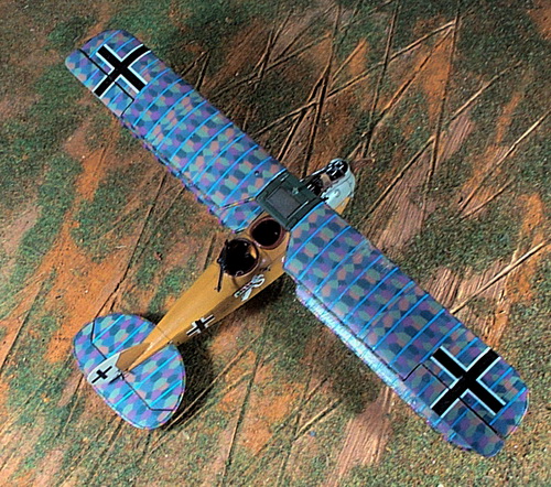
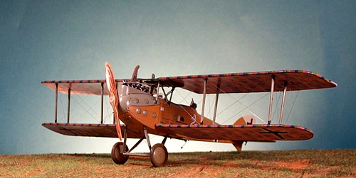

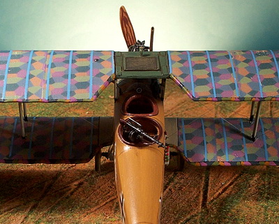
------------------------------------------------------------------------------------
FOOTNOTES
1 LVG C.VI design and construction notes are taken from German Aircraft of the First World War by Peter Gray & Thetford, 1962.
2 I would refer the reader to the complete Frontbestand introduced by Peter M. Grosz in WWI Aero Journal, issues 107 and 108. C-Types are found in issue 107.
3 For FA units, see Das Propellerblatt Heft (issue) Nr. 3; for FA(A) units, see Heft 5.
4 Grufl is short for Gruppenführer der Flieger or aviation group leader usually with the rank of major. See Cron page 406.
5 German ground units started the war in a traditional table of organization in the descending order: army, corps, brigade, regiment, and so on. The nature of combat at the beginning of the war transitioned in the late Fall of 1914 from one of mobility to one of immobility or static, trench warfare. When a corps was given a specific sector to hold, it might require more or less assets than its neighbor depending on terrain and tactical arrangements of the line. Since "corps" had a specific meaning in German military organization, adding assets meant that is was now more than a "corps". The army corps now became an element of the "Gruppe" which absorbed substantial elements including additional corps, divisions, artillery, pioneers, and machine gun assets, to name a few. A German Gruppe was often named after its commander or its geographical location. Gruppe Brimont had XV Armee Korps as its central infantry formation and a large number of attached assets including Grufl 10. See Cron page 90.
6 Casualties of the German Air Service 1914-1920 does not identify the cause of these two crashes. See page 324.
7 The French Air Service War Chronology 1914-1918 lists day-by-day French victory claims and losses. Most of the pertinent claims for 31 October and 1 November 1918 simply list the victorious pilot or pilots, their unit, the German aircraft shot down (simply "2 seater" in most cases), a location, and sometimes the time of day. See pages 324-325.
BIBLIOGRAPHY
Axelrod, Alan. World War I. Indianapolis: Macmillan USA, Inc, 2000.
Cron, Hermann. Imperial German Army 1914-18. Solihull, West Midlands, UK: Helion & Company, 2002.
Fliegertruppe website 21 Feb 2009, www.fliegertruppe.de
Franks, Norman; Frank Bailey, and Rick Duiven Casualties of the German Air Service 1914-1920. London: Grub Street, 1999.
Franks, Norman; Frank Bailey, and Russell Guest. Above the Lines. London: Grub Street, 1998.
Gray, Peter and Owen Thetford. German Aircraft of the First World War. London: Putnam & Company, Ltd., 1962.
Grosz, Peter M. Windsock Datafile 17 LVG C.VI. Berkhamsted, Hertfordshire, UK: Albatros Publications, Ltd., 1999 revised edition.
Grosz, Peter M. Archiv: Frontbestand. The Journal of the Early Aeroplane "WWI Aero", issues 107 (Dec 1985) and 108 (Feb 1986).
Kastner, Reinhard. Das Propellerblatt Nr. 1 "Markierungen (1): die bayer. Fliegerabteilung (A)286 im Jahre 1918", 2001.
Rimmel, Ray. Windsock Datafile 138 LVG C.VI at War. Berkhamsted, Hertfordshire, UK: Albatros Publications, Ltd., 2009.
Zankl, Reinhard. Deutsche Flieger-Einheiten 1914-1918: Folge 3 - Flieger-Abteilungen. Das Propellerblatt Nummer 3, 2002.
Zankl, Reinhard. Deutsche Flieger-Einheiten 1914-1918: Folge 5 - Artillerie Flieger-Abteilungen. Das Propellerblatt Nummer 5, 2002.
|
|
|
Model Cellar 1:48 German Luftstreitkräfte Pilot in Overall Flying Suit |
GO TO?